MONTAGGIORAMPEDISALITAEARRESTIFERMARUOTA
Lerampedisalita(pos.41,Fig.56)egliarrestifermaruota(42)pos
-
sonoesseremontatidaambolepartidellepedane(7-8)secondo
lenecessitàdell’utilizzatore.Procederealmontaggioincastrando
sullatodesideratolerampedisalita(41)efissaretramitevitiTE
M10x25(43),rosetteØ11x30(44)edadiM10(45)gliarrestifer
-
maruota(42)sullatoopposto.
Serichiestomontarelevitidiregolazioneperlaposizioneaterra
(50e51).
Fig.56 Fissaggiorampeebloccaggiruote
REGISTRAZIONEFUNI
Fig.57:saliresulponteconun’autovettura.
Posizionarsiall’altezzamassimaeverificarechei4martel-letti(32)
sianoalloggiatidentroleasoledelleastedisicurezza(12).
Verificarecheladistanzatraimartelletti(32)eleasoledelleaste
disicurezza(12)sulle4colonne(1-2-3-4)sia20mmminimodal
suoappoggio(fig.57)unamisurainferiorenondarebbeiltempo
allasicurezzariruotarerimanendoagganciataall’asta.
Senecessarioprocedereallivellamentoagendosuidadi(20)dei
terminali(19)dellefuni(33)eregolandoilmicrointerruttorefinecor-
sa.
Aregistrazioneultimatabloccareconicontrodadi(35).
IMPORTANTE:Questaoperazionediregistrazioneéda
ripeter-sidopo1o2settimanedallamessainserviziodel
sollevatore.
Fig.57 Registrazionefuni
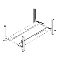
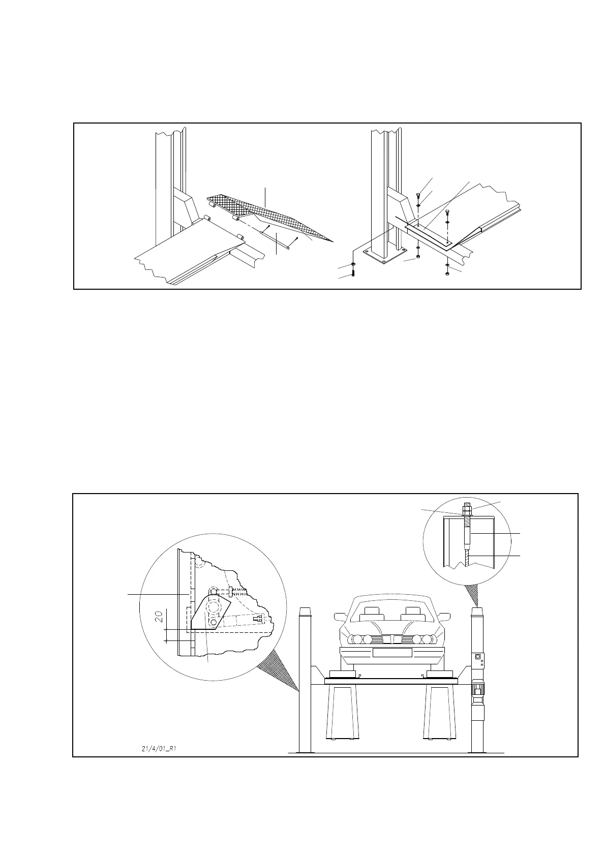
INSTALLINGTHEVEHICLERAMPSANDTHEWHEELSTOPS
Thevehicleramps(pos.41,fig.56)andthewheelstops(42)canbe
fittedoneitherendofplatforms(7-8)accordingtotheuser’sre
-
quirements.Fittheramps(41)byslottingthemintotheplatforms
ontherequiredendandthenfixthewheelstops(42)ontheoppo
-
siteendusingM10x25H.H.screws(43),11x30washers(44)
andM10nuts(45).
Ifrequeredfittheregulationscrewsforgroundpositionament(50
and51).
Fig.56 Securingthevehiclerampsandwheelstops
ADJUSTINGTHELIFTINGCABLES
Fig. 57:driveavehicleontothelift.
Raisethelifttothemaximumheightandcheckifthefourwedges
(32)arefittedinsidetheslotsofthesafetyrods(12).
Checkifthedistancebetweenthewedges(32)andtheslotsofthe
safetyrods(12)onthe4posts(1-2-3-4)isatleast20mmfromthe
support(fig.57);alowervaluewouldnotallowthesafetydeviceto
rotate,anditwouldstayattachedtotherod.
Ifnecessary,leveltheunitbyadjustingthenuts(20)onthetermi-
nals(19)ofthecables(33)andthelimitmicroswitch.
Whentheadjustmentiscompleted,lockwiththelocknuts(35).
IMPORTANT:Thisadjustmentmustberepeated1or2weeks
aftersettingupthelift.
Fig.57 Adjustingtheliftcables
31
12
32
20
35
19
33
41
47
46
45
43
44
44
42
51
50
 Loading...