CAP. 4 INSTALLAZIONE
I
ATTENZIONE
Prima di procedere all’ installazione del sollevatore, togliere l’ im
-
ballo e controllare la merce.
REQUISITI PER L’ INSTALLAZIONE
Il sollevatore deve essere installato rispettando le distanze di sicu
-
rezza da muri, colonne, altre macchine etc.
La distanza minima dai muri, considerando lo spazio per lavorare
comodamente deve essere almeno di 1000 mm. Bisogna poi con
-
siderare gli spazi per la postazione di comando, per le vie di fuga
in caso di emergenza. Il locale deve essere preventivamente predi
-
sposto per l’ alimentazione elettrica.
Il sollevatore può essere piazzato su qualsiasi tipo di pavimento,
purchè lo stesso sia perfettamente piano, orizzontale, nonchè di
resistenza adeguata ( min. 250 Kg. x cm2.).
x
Posizionare il ponte nel punto desiderato seguendo le indicazio
-
ni riportate sopra .
x
Montare i salvapiedi
x
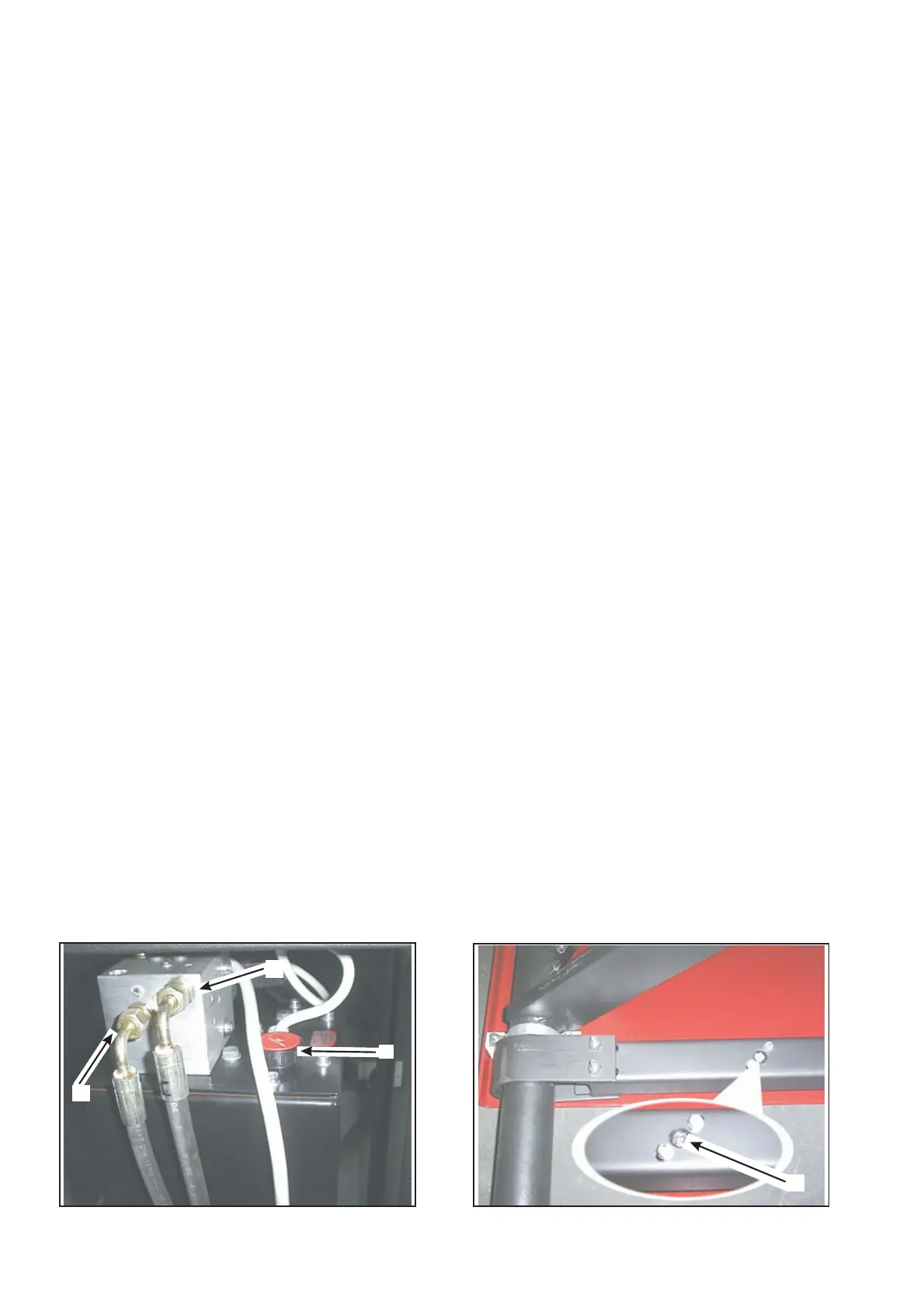
Collegare i tubi idrauliciAeBsulla centralina posta sul carrel
-
lo(fig. 9)
x
Svitare il tappo dell’olio ( pos.C fig.9) ed inserire olio nella cen
-
tralina con imbuto introdurre circa 4 Kg di olio idraulico tipo “
ESSO NUTO H 32 “ o equivalente .
x
Collegare elettricamente il cavo all’impianto elettrico (vedere
schema elettrico pag.9)
ATTENZIONE ! Il collegamento deve essere effettuato da per
-
sonale qualificato
ATTENZIONE ! L’impianto di rete deve essere in conformità
alle Norme e deve essere dotato dei fusibili relativi ( vedere
schema elettrico )
ATTENZIONE !Non invertire il neutro (azzurro) con le fasi
x Effettuare un sollevamento a vuoto della pedana ; in caso di
mancato funzionamento , invertire una fase al fine di permettere
la corretta rotazione del motore .
Nella prova di funzionamento a vuoto verificare anche il corretto
funzionamento delle sicurezze meccaniche .
Se premendo il pulsante di discesa, l’azionamento delle sicure non
è immediato, spurgare l’aria dai cilindretti delle sicure mediante lo
svitamento del tappo (fig.10 pos.D), quindi azionare la salita/disce
-
sa. Lasciare uscire aria e richiudere i tappi.
Tenendo la pedana in posizione di sollevamento massimo forare il
pavimento con punta elicoidale diametro 15 mm. per una profondi
-
tà di 70 mm. usando come dima i fori posti sulla base .
Pulire i fori , inserire i tasselli ( tipo Fischer GM 10 o equivalenti ) e
quindi serrare con una coppia di serraggio di 20 Nm.
Fig.9
CHAPTER 4 INSTALLATION
I
WARNING
Unpack the goods and check for possible damage before installing
the car lift.
INSTALLATION REQUIREMENTS
The car lift must be installed according to the specified safety di
-
stances from walls, columns, other equipments, etc. The minimum
distance from walls must be 1000 mm at least, taking into conside
-
ration the necessary space to work easily. Further space for the
control site and for possible runways in case of emergency is also
necessary. The room must be previously arranged for the power
supply.The car lift can be placed on any floor, as long as it is per
-
fectly level and sufficiently resistant (250 Kg X sq.cm. min).
x
Place the car lift as required following the instructions above in
-
dicated.
x
Fit the foot guards.
x
Connect hydraulic hoses Aand B to the power unit .( see fig.9)
x
Unscrew the oil tank cap (pos.C Fig.9) and, using a funnel, pour
about 4 lt of “ESSO-NUTO H32” hydraulic oil or equivalent.
x
Connect the electrical cable to the electric plant (see electric dia
-
gram at page 9).
ATTENTION ! Skilled personnel only is allowed to perform this
operation.
ATTENTION !The installation must comply with the regula
-
tions in force and must be equipped with relevant fuses (see
electrical intsllation).
ATTENTION! Do not invert the neutral (blue) with the phases.
x Lift the platform without any weight on it; in case the lift does not
work, change one phase in order to let the motor rotate in the
proper direction.
During this test withou any weight, check also the correct operation
of the mechanical safety devices.
When pushing the lowering button if the safety devices are not
immediately activated, it is necessary to bleed the air from the
cylinders of the safety devices, by unscrewing the plug (fig.10 pos.
D), then push the lifting/lowering button. Let the air come out and
screw the plugs again.
Keeping the platform in the highest position, drill the floor with an
helical bit having a diam. of 15 mm for a depth of 70 mm, using the
holes made on the base as a template.
Clean the holes, insert the anchor bolts (type Fischer GM 10 or
equivalent) and then tighten with a torque wrench of 20 Nm.
Fig.10
12
A
B
C
D
 Loading...