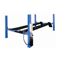
CAP. 5 FUNZIONAMENTO
I comandi del sollevatore sono situati sulla centralina di comando,
dove trovano alloggiamento: il gruppo motore-pompa idraulica,
e gli attacchi per l’allacciamento alla rete elettrica ed idraulica.
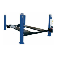
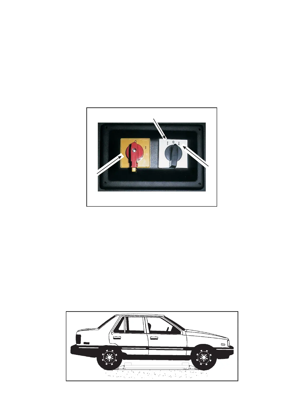
I comandi sulla consolle sono rappresentati in fig.11:
1- POSIZIONE DI SALITA:
Tipo “ uomo presente“ funziona sotto tensione,eseazionato, il
motore e i meccanismi attuano la salita del sollevatore.
2- INTERRUTTORE GENERALE:
POSIZIONE“0“:Ilsollevatore non è in tensione, ed è possibile
lucchettare l’ interruttore per impedire l’ uso del sollevatore in caso
di guasto.
POSIZIONE“1“:Ilsollevatore è in tensione.
3- POSIZIONE DI DISCESA:
Tipo “uomo presente“ funziona sotto tensione,eseazionato, i
meccanismi attuano la discesa del sollevatore.
Fig.11
SEQUENZA DI FUNZIONAMENTO
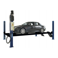
Prima di salire/scendere dal sollevatore, assicurarsi che le pedane
siano alla minima altezza.
Salire con l’ autovettura sul sollevatore a “ passo d’ uomo “, posi-
zionando la stessa come indicato in fig. 12.
Posizionare gli appositi tamponi in gomma sulla pedana del solle
-
vatore in corrispondenza dei punti di presa consigliati dal costrutto
-
re dell’ autovettura.
Spegnere il motore e innestare il freno di stazionamento dopo aver
posizionato l’ auotovettura sul ponte sollevatore e ricordarsi di di
-
sinserire la leva del cambio posizionandola sul “ folle “.
In fase di salita/discesa, il sollevatore deve essere costantemente
osservato insieme al suo carico.
Azionare il selettore di salita e portare il sollevatore alla altezza de
-
siderata . Per la discesa, qualora il sollevatore non sia nella posi
-
zione di massima altezza, selezionare “salita” e salire per un breve
tratto al fine di disinserire la sicura e quindi selezionare “discesa”
ATTENZIONE:la sicura deve essere disinserita in fase di di
-
scesa.
Fig.12
CHAPTER 5 OPERATION
Car lift controls are located in the control box, where the motor-
hydraulic pump unit and the connections to the electric and hydrau
-
lic system are also located.
Controls on the board are the following fig.11:
1 - LIFTING POSITION:
“Dead man control”, when pushed, the motor and the lifting
mechanism are operated.
2 - MAIN SWITCH:
“O” POSITION: lift is not powered. The switch can be padlocked to
prevent the use of the lift in case of failure.
“1" POSITION: lift is powered.
3 - LOWERING POSITION:
“dead man control”, when operated, the mechanism realize the
lowering .
OPERATION SEQUENCE
Make sure the platforms are at the minimum height before lif-
ting/lowering the car lift.
Get on the vehicle and crawl on the car lift; be sure the vehicle is
centred and both rear and front wheels are properly positionated
(see fig.12).
Place the proper rubber pads on the platform so that they are in
line with the lifting points specified by the manufacturer (see picture
below).
Switch off the engine and engage the parking brake after placing
the vehicle on the car lift; furthermore disengage the shift lever and
move it to the “neutral” position.
Carefully check the car lift and its load during lifting/lowering opera
-
tions.
Push the lifting button and stop the lift at the required height. To
lower, if the lift is not at the max. height, select the lifting button in
order to release the safety devices and then push the lowering but
-
ton.
ATTENTION: The safety devices must be released when
lowering
13
1
3
2
 Loading...