CAP.1. DESCRIZIONE DELLA
MACCHINA
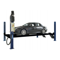
Il sollevatore elettroidraulico è fisso, cioè ancorato al suolo ed è
progettato e costruito per il sollevamento e lo stazionamento in
quota di autoveicoli.
Il funzionamento è di tipo elettroidraulico.
Il sollevatore è composto, principalmente dalle seguenti parti:
x
gruppo struttura fissa ( basamento )
x
gruppi mobili (leve+piani di sollevamento )
x
gruppi di sollevamento (cilindri idraulici e centralina);
x
quadro comando
x
sicurezze.
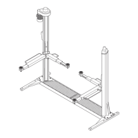
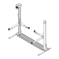
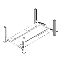
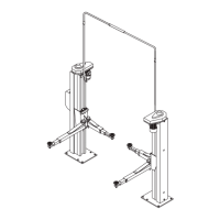
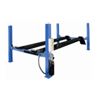
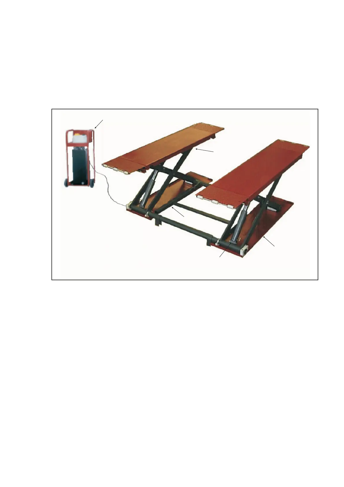
In figura 4 sono indicate le varie parti che compongono il sollevato
-
re.
Fig.4
GRUPPO STRUTTURA FISSA
E’ costituito da un basamento (1) costruito in lamiera di acciaio sal
-
data, con fori per il fissaggio al suolo mediante tasselli ad espan
-
sione (vedere cap.4 “installazione”). All’interno del basamento si
trovano i fori per l’attacco dei bracci di sollevamento.
GRUPPO MOBILE
E’ costituito da due piattaforme e da bracci in piatto saldato (2),
collegati alle estremità mediante alberi ed ancorati al basamento
tramite supporti in materiale plastico.
Un sistema di sicurezza (3), collegato al braccio trainante e aziona
-
to mediante cilindri idraulici, si inserisce automaticamente durante
tutta la fase di salita e blocca il sollevatore durante lo stazionamen
-
to in quota.
GRUPPO DI SOLLEVAMENTO
É costituito da 2 cilindri idraulici (4) collegati mediante tubi rigidi e
flessibili ad una centralina idraulica.
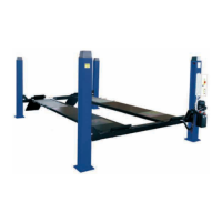
Il gruppo di sollevamento è comandato per mezzo di un quadro
elettrico di comando (5) posto su un carrello contenente la centrali
-
na.
SICUREZZE
Le sicurezze sono costituite da :
x
una sicurezza meccanica
x
una valvola idraulica di massima pressione
x
una valvola strozzatrice compensatrice che regola la discesa
x
un dispositivo acustico
x
i salvapiedi
CHAP. 1 DESCRIPTION OF THE
MACHINE
The electro-hydraulic lift, is a fixed installation; this means that it is
anchored to the ground and designed and built for lifting and posi
-
tioning automobiles at a certain height off the ground.
The lift is driven by an electro-hydraulic operating system.
The lift consists of the following main parts:
x
fixed structure (base);
x
mobile units (levers+lifting platforms);
x
lift units (hydraulic cylinders and hydraulic unit);
x
control box;
x
safety devices.
Figure 4 illustrates the various parts making up the lift.
FIXED FRAMEWORK UNIT
It is composed of a base (1) made of welded steel plates, with ho
-
les for fixing to the ground by means of expanding plugs (see chap.
4 “installation”). Inside the base there are holes for the attachment
of the lifting arms.
MOBILE UNIT
It is composed of two platforms and levers of welded steel plates
(2), connected at the ends by means of shafts and connected to
the base by means of special plastic supports. A security system
(3), connected to the towing arm, and driven by means of hydraulic
cylinder, is automatically inserted during the whole lifting phase
and locks the lift during parking at a height.
LIFTING UNIT
It is composed of two hydraulic cylinders (4) connected by rigid and
flexibles tubes.
The lifting unit is controlled by an electric panel (5) placed on a car
-
riage containing the hydraulic unit.
SAFETY DEVICES
The safety devices are composed of:
x
a sprag to lock the lift at a height.
x
a max pressure hydraulic valve
x
a compensated throttle valve which adjusts lowering
x
an acoustic device
x
the footguards
5
1
2
3
4
5
 Loading...