7
O.M.A.C. s.r.l.
Via Giovanni Falcone, 8 42048 Rubiera (RE) - Italy Tel.0522/629371 - 629923 Fax 0522/628980
E-mail:info@omacpompe.com SitoWeb:www.omacpompe.com
Rev.4 del 01/2011 O.M.A.C. s.r.l.
Chap.1 - pag.
1.3.6 Tightening torque
This table shows the tightening torque values, to be used as reference during all assembly and disassembly operations of pump components, in one or
more parts.The values mentioned in the table below relate to gear adjustment, rotor blocking, pumping body blocking, front cover blocking, bearing ring
blocking and gear ring blocking.
PUMP MODEL
GEAR ADJUSTMENT
(pos.8, pag.15)
ROTOR LOCKING
(pos.42, pag.15)
PUMPING CASE LOCKING
(pos.52, pag.15)
FRONT COVER LOCKING
(pos.51, pag.15)
Thread
d x pitch
Key type
/ Size [mm]
TORQUE
[Nm]
Thread
d x pitch
Key type
/ Size [mm]
TORQUE
[Nm]
Thread
d x pitch
Key type
/ Size [mm]
TORQUE
[Nm]
Thread
d x pitch
Key type
/ Size [mm]
TORQUE
[Nm]
B100 M4X0.7 A/7 3 M8X1 A/17 25 M6X1 A/10 10 M6X1 A/10 10
B105 B110 B115 M5X0.8 B/4 5 M12X1 A/27 85 M8X1.25 A/13 30 M8X1.25 A/13 30
B215 B220 M6X1 B/5 10 M14X1.5 A/30 190 M10X1.5 A/17 50 M10X1.5 A/17 50
B325 B330 B390 M8X1.25 B/6 20 M20X1.5 A/38 305 M12X1.75 A/19 70 M10X1.5 A/17 50
B430 B440 M10X1.25 B/8 50 M24X2 A/46 480 M16X2 A/24 115 M12X1.75 A/19 70
B470 B490 M10X1.25 B/8 50 M24X2 A/46 480 M20X2.5 A/30 180 M14X2 A/22 95
B550 M12X1.75 A/19 70 M24X2 A/46 500 M14X2 A/22 115 M12X1.75 A/19 70
B660 B680 M16X2 A/24 170 M36X2 A/60 600 M14X2 A/22 115 M14X2 A/22 70
PUMP MODEL
BEARING RING NUT LOCKING
(pos.21, pag.15)
GEAR RING NUT LOCKING
(pos.42, pag.15)
Thread
d x pitch
Key type
/ Size [mm]
TORQUE
[Nm]
Thread
d x pitch
Key type
/ Size [mm]
TORQUE
[Nm]
B100 - - - M20X1 HN4 50
B105 B110 B115 M30X1.5 HN6 90 M30X1.5 HN6 90
B215 B220 M40X1.5 HN8 105 M35X1.5 HN7 90
B325 B330 B390 M50X1.5 HN10 115 M40X1.5 HN8 105
B430 B440 M70X2 HN14 220 M60X2 HN12 145
B470 B490 M80X2 HN16 400 M70X2 HN14 220
B550 M70X2 HN14 220 M70X2 HN14 220
B660 B680 - - - M100X2 HN20 600
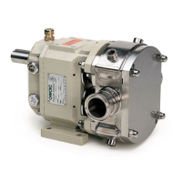
1.3.7 Mechanical seals overall dimensions
Below there are the overall dimensions of the mechanical seals fi tted on the B series lobe pump, according to the size of the pump and the position of
the seal. The drawing below shows the references relative to the main dimensions of the mechanical seals, whose values, in mm, are shown in the table,
according to the size of the pump.
B100
B105
B110
B115
B215
B220
B325
B330
B390
B430
B440
B470
B490
B550
B660
B680
d1 20 30 35 50 65 80 65 100
d6 29 39 44 62 77 95 77 115
d7 35 45 50 70 85 105 85 125
L1 29.1 29.1 29.1 34.1 38.8 43.8 38.8 41.3
L2 44 44 44 50 55.5 59 55.5 85
L3 19.1 19.1 19.1 21.1 25.8 25.8 25.8 25.8
L4 10 10 10 13 13 18 13 15.5
L5 2 2 2 2.5 2.5 3 2.5 3
L6 5 5 5 6 6 7 6 7
L7 9 9 9 9 9 9 9 9
The “A” type spanner - ref. “spanner type” column - is a
polygonal spanner; the “B” type spanner - ref. “spanner
type” column - is hexagonal (inbus or imbus).
With regard to the tightening torque value of the elemen-
ts that make up the LDPU, please refer to the use and
maintenance manuals (fl exible transmission coupling,
motorisation).
NOTE