FM Transmitter
Sistemas Electrónicos S.A EM 250 COMPACT DIG
Technical Manual - v1.1 - February 2006 32
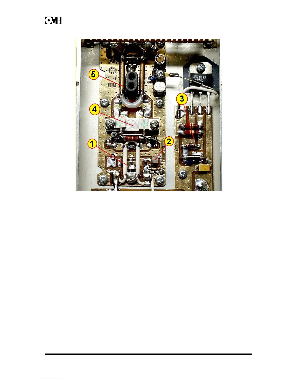
Fig. 2-5: DETAIL OF OUTPUT AMPLIFIER SECTION.
Elements numbered in Figure 2-5 can be described as follows:
1 - Input splitter transformer and coupling circuit.
2 - Bias adjustment potentiometer.
3 - Bias regulator circuit.
4 - MOSFET push-pull arranged, twin-transistor capsule.
5 - Output combiner transformer and matching circuit.
Following this amplifier stage, module includes a low-pass filter in order to attenuate or suppress all
harmonics and IM products beyond Band II limits, as shown in Figure 2-6.