5. Using Isolated Measure Modes (Upper Display)
5.1 Measuring volts and mA
Use the following steps to measure the voltage or current output of a
transmitter.
1. Select the upper display from the Main Menu.
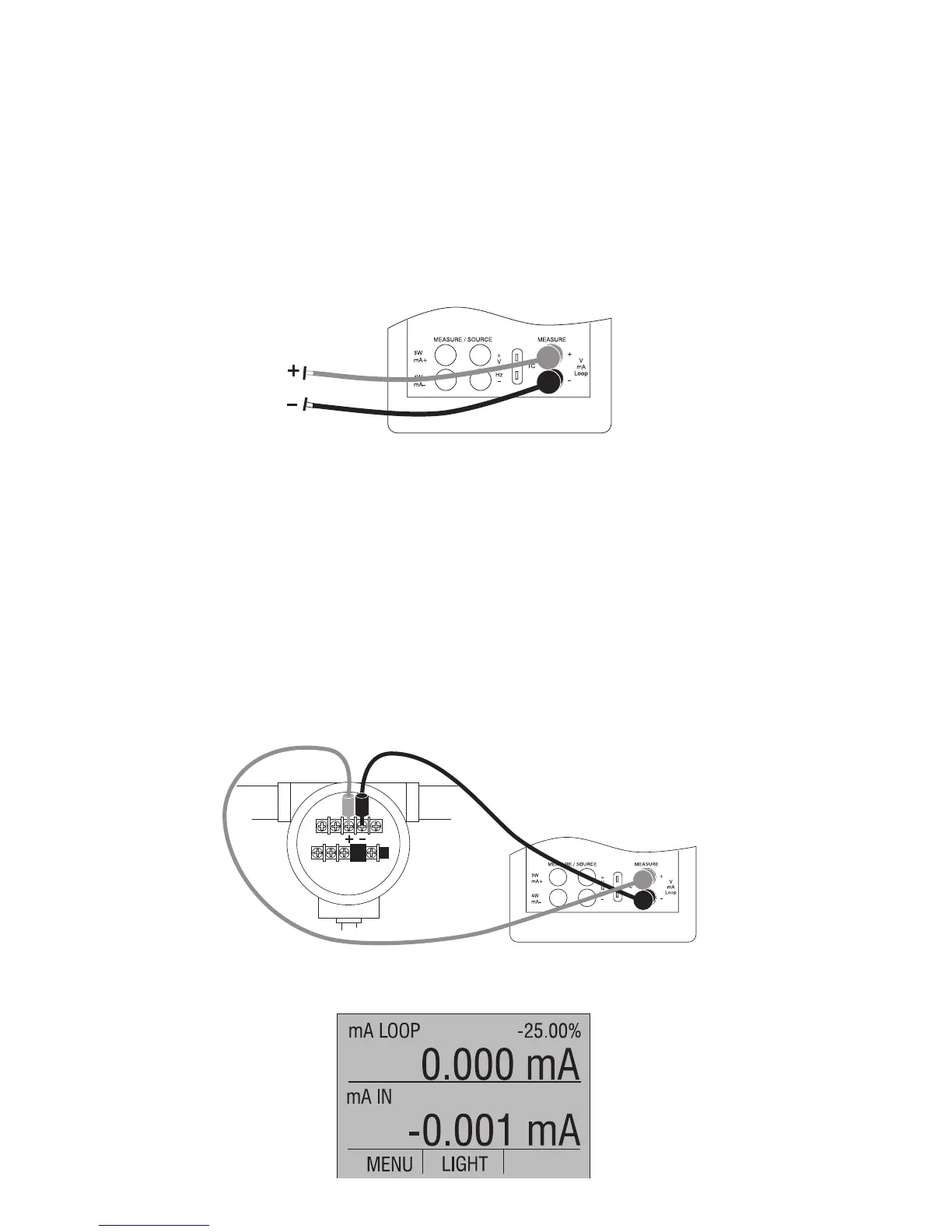
2. Select the desired primary parameter to be measured. Connect
the leads to the isolated inputs of the calibrator, as in Figure 16.
Figure 16. Isolated Input Connection
5.2 Measuring current with loop power
To test a 2-wire, loop powered transmitter that is disconnected from
wiring, use the loop power function. This function activates a 24V
supply in series with the current measuring circuit. To use this option
proceed as follows:
1. Select [mA LOOP] as primary parameter in the upper display.
2. Connect the calibrator to transmitter current loop terminals, as
shown in Figure 17.
Figure 17. Connection Using Current Loop
24