FEATURES OVERVIEW:
The 4 Relay Output Board provides four isolated
Form-C electro-mechanical relays that enable
setpoint-triggered switching to an external device.
Each relay can accommodate a single setpoint.
200 W, 2500pf snubbers are provided for each
normally open contact.
BOARD INSTALLATION:
To install optional Relay Output printed circuit board:
1.
Refer to “Reveal the Main Board” in Main Operator’s
Manual Section 5.2, Disassembly.
2.
Using figure below as a reference, insert relay option
board(s) into J10 connector on the main board.
WARNING: To avoid electrical shock be sure
to disconnect the unit from its power supply.
After you have opened the meter you are
ready to install option card.
To install:
1. Hold relay board with components facing the main
board.
2. Position the P10 connector to mate with the J10
connector on the main board (at rear of unit).
3.
Push the board downward, guiding relay board
edges through the rear panel guides until it rests on
the upper rear panel and the main board.
Figure 1 Option Board Installation
4 RELAY OUTPUT BD
SIGNAL INPUT BD
AC POWER BD
P10
J10
Start Here
JUMPER CONFIGURATION:
The figure below shows the locations of the 4 Relay
Output Board jumpers S1 and S2, the P10 socket
connecting the board to the Main Board, and the
output plugs P6, P7, P18A and P18B.
Press This Button
Figure 2 4 Relay Board Jumpers and Plugs
The table below shows which jumpers are assigned
to each relay. Defaults have asterisks.
re 4 Relay Output Board Wiring Connections
Table 1 4 Relay Board Jumpers
S1 S2 FUNCTION
Assigns SP1 to Relay 1 (P6)
A, C* A, C* Assigns SP2 to Relay 2 (P7)
Assigns SP3 to Relay 3 (P18A)
Assigns SP4 to Relay 4 (P18B)
Assigns SP1 to Relay 3 (P18A)
B, D A, C Assigns SP2 to Relay 2 (P7)
Assigns SP3 to Relay 1 ( P6)
Assigns SP4 to Relay 4 (P18B)
Assigns SP1 to Relay 3 (P18A)
B, D B, D Assigns SP2 to Relay 4 (P18B)
Assigns SP3 to Relay 1 ( P6)
Assigns SP4 to Relay 2 ( P7)
Assigns SP1 to Relay 1 (P6)
A, C B, D Assigns SP2 to Relay 4 (P18B)
Assigns SP3 to Relay 3 (P18A)
Assigns SP4 to Relay 2 (P7)
A
B
C
D
S1
S2
B
D
A
C
S
1
S2
P18B
P18A
P7
P6
P10
2
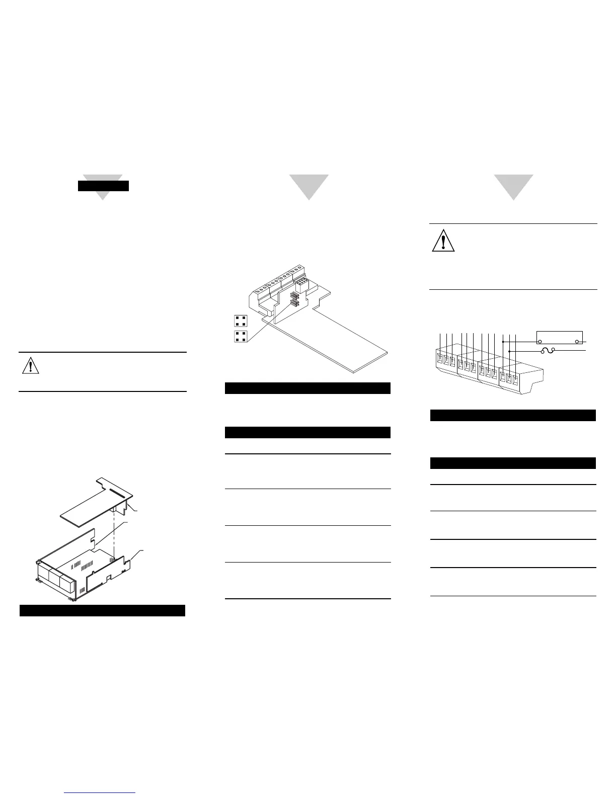
WIRING CONNECTIONS:
WARNING: Do not connect ac power
meter until you have completed all input
and output connections. Failure to do so
may result in injury! This device must only
be installed electrically by a specially
trained electrician with corresponding
qualifications.
Press This Button
Figure 3 4 Relay Output Board Wiring Connections
Table 2 Pin Assignments for the P6, P7 and P18
CONNECTOR PIN FUNCTION
P6 1 NO1 (Normally Open)
(Relay 1 Connection) 2 Common 1
3 NC1 (Normally Closed)
P7 1 NO2 (Normally Open)
(Relay 2 Connection) 2 Common 2
3 NC2 (Normally Closed)
P18A 1 NO3 (Normally Open)
(Relay 3 Connection) 2 Common 3
3 NC3 (Normally Closed)
P18B 1 NO4 (Normally Open)
(Relay 4 Connection) 2 Common 4
3 NC4 (Normally Closed)
1
2
3
1
2
P18A
P18B
3
}
}
Relay 3
Relay 4
N.O.3
COM3
N.C.3
N.O.4
COM4
N.C.4
EXTERNAL LOAD
N
L
FUSE
N.O.4
COM4
1
2
3
1
2
P6
P7
3
}
}
Relay 1
Relay 2
N.O.1
COM1
N.C.1
N.O.2
COM2
N.C.2

 Loading...


