
C
Cody RhodesAug 3, 2025
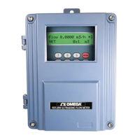
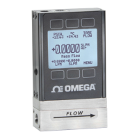
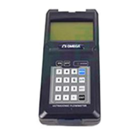
What to do if Omega FDT-25 Measuring Instruments shows a Stored Data Error?
- EEmily SmithAug 3, 2025
If your Omega Measuring Instruments displays a 'Stored Data Error', it indicates that the parameters you entered have lost integration. To resolve this, press the ENT key. This action will restore all configurations to their default state.