
M
Megan GrimesAug 5, 2025
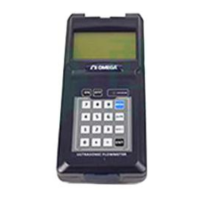
What to do if I see a 'Stored Data Error' on my Omega FDT-25W Measuring Instruments?
- Ffrederick39Aug 5, 2025
If you receive a 'Stored Data Error' message on your Omega Measuring Instruments device, it means the parameters you entered have lost integration. To resolve this, press the ENT key. This action will restore all configurations to their default state.