Do you have a question about the Omegon MiniTrack Quattro NS and is the answer not in the manual?
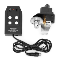
Lists the main components provided with the Omegon MiniTrack Quattro NS mount.
Details the components located on Side A of the MiniTrack Quattro NS mount.
Details the components located on Side B of the MiniTrack Quattro NS mount.
Ensures compatibility with standard tripod plates and proper mount positioning.
Importance of aligning the mount parallel to the adapter base for fine-tuning polar alignment.
Details on using the locking mechanism with the hex key and locking bolt.
Ensures the ball-head is securely tightened to prevent slippage during long exposures.
Procedure for attaching the camera with adapter to the ball-head's base.
Explains the importance of balancing the camera's center of gravity for accurate tracking.
Initial steps for pointing the mount towards Polaris for rough alignment.
Steps to precisely align the mount using the polar finder and tripod levellers.
Guide on how to identify Polaris in the night sky using constellations.
Explains how the spring system acts as a counterweight for tracking balance.
How to check if the timer can push the setup and when spring tension needs adjustment.
Guide on selecting the correct spring tension position for various load imbalances.
Specific spring tension recommendations for pointing East, South, and West.
Instructions for releasing thumbnuts and the timer screw for Southern Hemisphere setup.
Procedure for adjusting the winding knob and attaching the south arm for inverted tracking.
Final steps to secure the assembled arm to the timer mechanism.
Guide on selecting the correct spring tension position for various load imbalances.
Specific spring tension recommendations for pointing West and North.
Instructions to identify Crux and use it to locate the South Celestial Pole (SCP).
Steps to precisely align the mount to the SCP using the polar finder.
A summarized list of steps required to set up the Omegon Quattro mount.
Final adjustments to spring position and commencing astronomical shooting.
Details the mount's capacity for load and tracking duration up to 60 minutes.
Formula and table for calculating maximum exposure time based on objective focal length.
An example demonstrating how to calculate expected tracking time for a specific setup.
Provides links to online videos and Facebook groups for more information.
The Omegon® MiniTrack Quattro NS is a mechanical mount designed for wide-field astrophotography, suitable for beginners, intermediate, and advanced amateurs. Its compact and portable design makes it an ideal solution for on-the-go use, capable of operating in both the Northern and Southern hemispheres.
The core function of the MiniTrack Quattro NS is to "follow" or track the apparent movement of the night sky, enabling long-exposure astrophotography without star trailing. This is achieved through a built-in timer mechanism that rotates the camera setup. For successful tracking, the mount must be precisely aligned with either Polaris (the North Star) in the Northern Hemisphere or the South Celestial Pole (SCP) in the Southern Hemisphere. This process is known as polar alignment.
The mount sits on a tripod head, allowing for inclination adjustments, typically corresponding to the user's latitude. A ball head mount (not included) is required for the camera, enabling it to be easily pointed at desired celestial objects. Once the timer is wound up and the mount is properly aligned, it is ready for operation.
A key feature of the MiniTrack Quattro NS is its ability to operate in both hemispheres. The "NS" in its name signifies Northern and Southern Hemisphere compatibility. In the Southern Hemisphere, where the sky rotates in the opposite direction, an additional "South arm" (C) is attached to the mount, and the timer's movement sense is inverted to accommodate this change.
The mount incorporates a spring system that acts as a counterweight, providing additional push force to the timer, especially when the camera setup is slightly off-balance. This helps the timer track objects more conveniently and accurately. The tension of this spring can be adjusted based on the weight and balance of the camera setup, ensuring optimal tracking performance.
To begin using the MiniTrack Quattro NS, users should first familiarize themselves with its various components. The mount is compatible with any ¼" or ⅜" tripod plates. Before attaching a ball head, a tiny locking bolt (#18) must be released. This bolt is tightened using a supplied hex-key (A) to ensure the mount is locked before the ball head is threaded onto the ⅜" threaded ball head (#1).
Proper balance of the camera setup on the ball head is crucial for accurate tracking. The setup's center of gravity should ideally sit on an imaginary line to the center of the ball-head's base. If necessary, an additional Arca Swiss-type dovetail (not supplied) can be used to achieve this balance. The ball head itself must be securely fixed to prevent slippage during long exposures, with all its knobs tightened to prevent movement when installing the camera. The ball head's two additional knobs allow for precise adjustment of the camera's azimuth (360 degrees) and altitude, enabling users to point to any desired object in the sky.
For Northern Hemisphere configuration, the mount is roughly aligned with Polaris. The supplied polar finder (B) is then slid into the polar finder holder (#3) for more precise alignment. Polaris, though not the brightest star, can be identified by locating the Big Dipper constellation and extending a line from Merak and Duhbe. Fine-adjustment levellers on the tripod are used to center Polaris in the polar finder's visual field.
Balancing the mount on the East hemisphere is particularly important. If the setup's center of mass is slightly off to the west, the generated moment-arm aids the timer in tracking. However, if it's off-balanced to the east, the timer might struggle. The spring system compensates for this by adding push force. Users can determine if the timer is struggling by listening to its ticking sound with and without the load. The ticking tempo should be around 135 bpm, and the spring position can be adjusted to accelerate or slow down the tempo. Unnecessary spring tension should be avoided as it can alter the timer's clock tracking rate.
When pointing East, if the camera setup tends to rotate the ball-head counter-clockwise, the spring should be tensioned to one of the numbered teeth, with stronger tension for greater imbalance. For instance, in the worst-case scenario (position 5), a weight of up to 4kg can be balanced when pointing to the zenith with the camera body towards the east. When pointing South, the spring can be completely disengaged (position "0") or set to idle (position "1"). When pointing West, if a strong imbalance causes the timer to "accelerate," the "R" tooth can be used to compensate by braking the rotation motion.
For Southern Hemisphere configuration, the process involves several steps to invert the timer's movement. First, the two thumbnuts (#6 Side A) are released and removed. The timer screw with washer (#10) is then released and unscrewed using a Philips-style screwdriver. The winding knob (#7) is pushed away from the arm to slide the arm to the left, ensuring the spring does not impede this movement. The winding knob and timer screw/washer are removed. The winding knob is then turned 180 degrees (upside down) and screwed back with the timer screw and washer (#10 Side B), but not tightened yet. The South arm (C) is placed between the winding knob and the timer, aligning its protruding studs with the arm's through holes, ensuring the winding knob moves freely. Finally, the assembled arm is pushed back to its original position, keeping the winding knob "upside down," and the arm is pushed against the timer and winding knob against the teeth. The screw is then fixed in place with a Philips-style screwdriver, taking care not to overtighten it to avoid damaging the timer.
Aiming to the South Celestial Pole (SCP) involves identifying the Crux constellation. Users align the stars as shown in the manual and count 4.5 times its distance in the same direction to find the SCP. The polar finder (B) is used for precise alignment, and the tripod's fine-adjustment levellers help center the SCP in the visual field.
The manual emphasizes the importance of proper balance and spring tension adjustment for optimal performance, which can be considered a form of operational maintenance. Avoiding unnecessary spring tension helps maintain the timer's clock tracking rate. The locking bolt should always be released before use to prevent the winding knob from being locked. When reassembling components, such as the timer screw, care should be taken not to overtighten to prevent damage to the timer mechanism.
The MiniTrack Quattro NS is designed to carry setups up to 4kg and track for 60 minutes. Exceeding these limits can reduce tracking quality and total tracking time, leading to star trailing. The manual provides a formula for calculating maximum tracking time based on objective focal length (Time (min) = 100 / Objective focal length (mm)), which helps users understand the mount's capabilities and adjust their exposure times accordingly. This guidance helps users maintain the device within its operational parameters, contributing to its longevity and performance.
| Load Capacity | 3 kg |
|---|---|
| Material | Aluminum |
| Max. payload | 3 kg |
| Mount type | Vixen GP Level |
| Tracking speed | Sidereal rate |
| Compatibility | DSLR and mirrorless cameras |