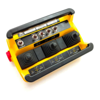
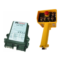
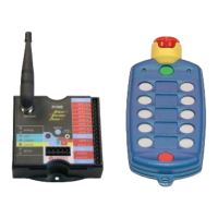
The OMNEX T300 / R160 / D160 system is a portable, long-range, programmable radio remote control system designed for industrial applications, particularly for crane operation. It is a robust, easy-to-install device with comprehensive self-diagnostics, functioning as a radio, a PLC, and a valve driver.
Function Description:
The system utilizes Frequency Hopping Spread Spectrum (FHSS) technology, which concentrates full power into a narrow signal that randomly hops across frequencies within a designated band. This, combined with CRC-16 error-checking, enhances signal reliability and helps overcome interference common with licensed radios. The T300 transmitter sends control signals, the R160 receiver processes them, and the D160 expansion module provides additional input/output capabilities. A unique ID code for each T300 prevents conflicts between multiple systems on a job site.
Important Technical Specifications:
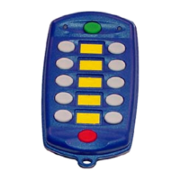
- T300 Transmitter:
- Dimensions: 9.5" x 6.0" x 5.0" (240mm x 152mm x 127mm)
- Weight: 3.5 lbs (1.2kg) including batteries
- Construction: High impact, low temperature plastic, weatherproof
- Battery Life: 500 hours (continuous use) with 4 "C" alkaline batteries
- Operating Temperature Range: -40°F to 140°F (-40°C to 60°C)
- Controls: Up to sixteen proportional and sixteen digital controls, eight single-axis paddles, eight three-position switches, and a resettable E-Stop.
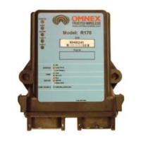
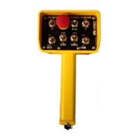
- R160 Receiver:
- Dimensions: 5.1" x 4.7" x 1.4" (130mm x 119mm x 36mm)
- Weight: 0.65 lbs (0.295kg)
- Construction: High impact plastic, weatherproof
- Input Power: +9V to 30VDC
- Outputs: 19 solid-state, high-side driver outputs; 5A max per pin, 7A max per bank, total combined current 15A. All output pins can be factory configured as inputs.
- Operating Temperature Range: -40°F to 158°F (-40°C to 70°C)
- Antenna: Internal
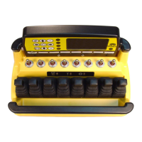
- D160 Expansion Module:
- Dimensions: 5.1" x 4.7" x 1.4" (130mm x 119mm x 36mm)
- Weight: 0.65 lbs (0.295kg)
- Construction: High impact plastic, weatherproof
- Input Power: +9V to 30VDC
- Outputs: 19 solid-state, high-side driver outputs; 5A max each, total combined current 15A. Up to 19 input/output (including 2 proportional) combinations, PWM, or voltage outputs. All output pins can be factory configured as inputs.
- Operating Temperature Range: -40°F to 158°F (-40°C to 70°C)
- Antenna: Internal
- General System:
- Approvals: FCC part 15.247 (USA), ISC RSS 210 Issue 6 (Canada), EN 440 (Europe), C-Tick (Australia)
- Range: 1200 feet @ 900 MHz (900 ft @ 2.4 GHz)
- License: License-free operation.
- Resilience: Resilient to impact and shock.
Usage Features:
- Installation: Simple "wire-and-use" installation. The receiver and expansion module can be mounted using two 1/4" bolts, ensuring the text is readable and connectors point down. Power connections (Power (+) and Ground (-)) should be made directly to the battery, avoiding existing wiring or peripheral connection points.
- Wiring: Output cables are provided to simplify wiring. Proper wire gauge and insulator type are crucial. Outputs should be tested with a multi-meter before connecting to end devices.
- Noise Suppression: Diodes (OMNEX part number AKIT-2492-01) should be installed across solenoid or electromagnetic switch terminals to prevent surges and spikes.
- Transmitter Operation: Batteries are installed by removing the cover and inserting 4 "C" alkaline batteries, observing polarity. Lithium batteries are recommended for temperatures below -10°C. The transmitter can also be powered via a pendant cable, eliminating the need for batteries. To turn on, ensure all switches and paddles are in neutral, then press and release the [Power] switch. The RED (E-Stop) light will flash quickly; releasing the [E-Stop] will cause the yellow (Active) light to flash.
- Link Test: A link between the transmitter and receiver is established when the transmitter's (Active) light flashes and the receiver's (Link) light flashes GREEN.
- ID Code Download: Necessary when replacing a transmitter or receiver. This process involves opening the R160 case, pressing the Setup button, and following a sequence of power-ups and button presses on both the transmitter and receiver. For safety, the transmitter must be in close proximity to the receiver during download.
- Proportional Control Calibration: Paddles/joysticks control proportional output. Calibration involves setting minimum and maximum levels by pushing the paddle, holding it, and pressing the [Power] switch UP or DOWN. Calibration settings can be reset to factory default.
- Automatic Shutdown: The transmitter will shut off after 4 hours of inactivity to save battery life. Momentarily operating any toggle switch or paddle will restart the timer.
Maintenance Features:
- Safety Precautions: Always provide a safety cutoff switch. Disconnect the radio from power during maintenance. Turn off receiver power before working on machinery to prevent accidental operation.
- Wiring Inspection: Regularly inspect for loose or frayed wires, which can cause system failure or intermittent operation.
- Environmental Considerations: Do not install in hot areas (above 158°F/70°C). Keep units dry and do not clean with high-pressure water. If water enters, immediately dry the unit by removing the case.
- Cleaning: Clean units after operation to remove mud, dirt, or concrete from buttons and switches using a damp cloth.
- Welding: Disconnect the radio receiver before welding on the machine it is connected to to prevent destruction of the receiver.
- Battery Replacement: Replace all batteries at the same time as a complete set; do not mix and match types.
- Troubleshooting Guide: Comprehensive charts are provided for diagnosing issues with the receiver and transmitter, including indicator light interpretations and recommended solutions for common problems like wiring faults, low battery, and internal faults.
- Fuse Replacement: The R160 receiver has a fuse (Bussman ATC-15, 36V Bi-directional, part number F0039) that can be replaced. Instructions for accessing the fuse are provided.
- Repair: For unrecoverable faults or persistent issues, the manual advises returning the unit for service.