00038393.DOC, Version 1.0
26/36
In order to obtain highest sound quality, only use high-quality cables for connecting the devices. Make sure
that the cables are properly fixed.
Mic In
Here, you can connect dynamic microphones via balanced microphone-cables.
The microphone signals are connected via the XLR-socket.
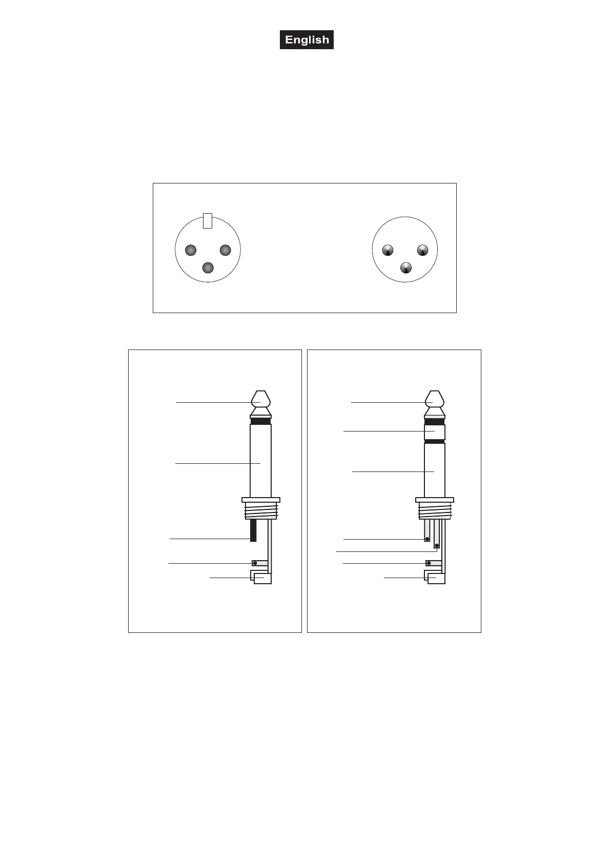
Occupation balanced XLR-connection:
2
1
3
1
2
3
BalancedusewithXLRconnectors
1=Ground/Shield
2=Hot(+)
3=Cold(-)
Forunbalancedusepin1andpin3havetobebridged
Input Output
Occupation jack plug:
Unbalanceduseof
mono1/4"jackplugs
Tip=
Signal (+)
Sleeve=
Ground/Shield
Tip
Sleeve
Strainreliefclamp
Balanceduseof
Tip=
hot(+)
Sleeve=
Ground/Shield
Tip
Sleeve
Strainreliefclamp
stereo1/4"jackplugs
Ring=
cold(-)
Ring
Forconnectionofbalancedand
unbalancedplugs,ringandsleevehave
tobebridgedatthestereoplug.
Line In
The Line In can either be connected via the balanced XLR mounting-socket.
Line Out
Connect the Line output via the balanced XLR-plug. The connection with the next active speaker should be
made via a microphone cable.
INSTALLATION
This speaker-system must only be installed at a solid, plane, anti-slip, vibration-free, oscillation-free and fire-
resistant location.