00043864.DOC, Version 1.1
25/32
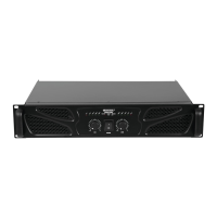
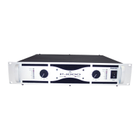
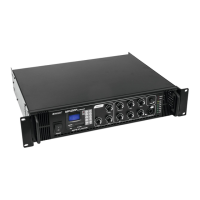
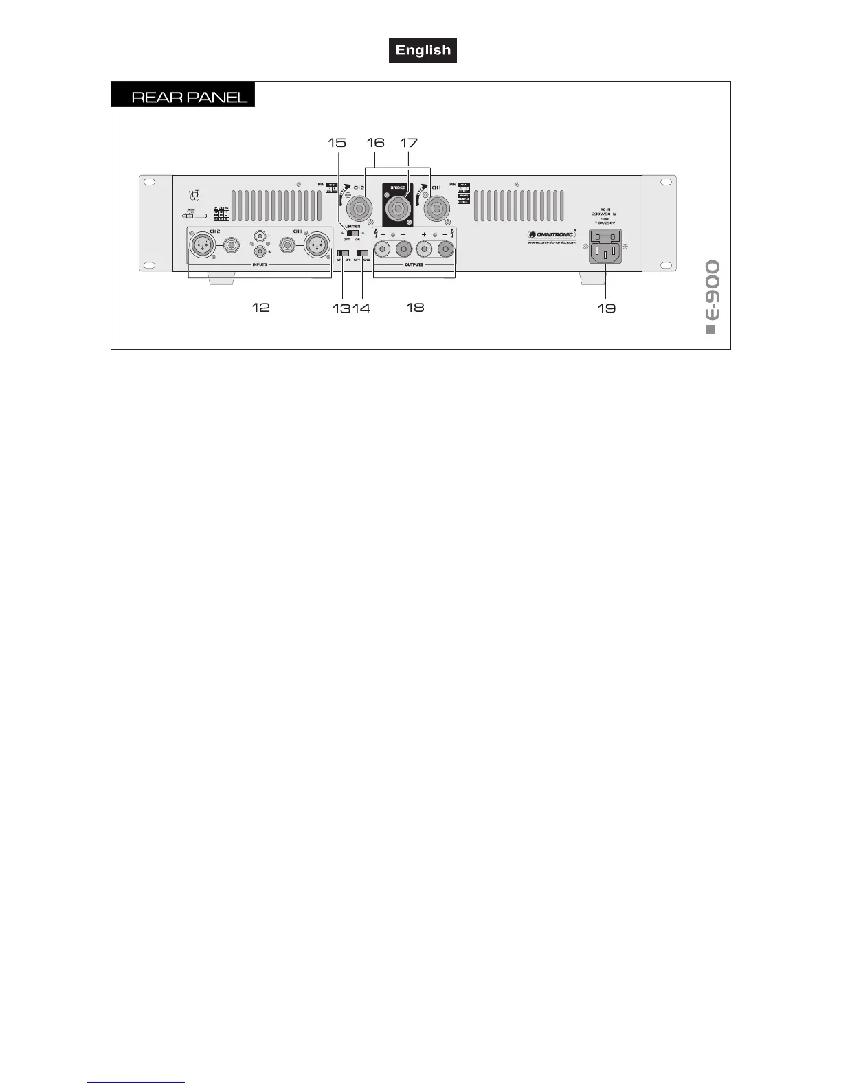
Input jacks
Inputs for channel 1 and 2 for connecting units with line
level
Models E-200, E-300, E-600 and E-900: optionally XLR,
6.3 mm jack or RCA
Model E-1300: optionally XLR or 6.3 mm jack
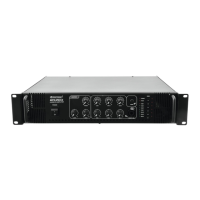
13 Selector switch operating mode
• position STEREO: stereo operation
• position BRIDGE: bridge operation
14 Selector switch ground lift
• position LIFT: signal ground and housing ground are
separated
• position GND: signal ground and housing ground
are connected
15 Selector switch limiter
• left position: limiter is switched off
• right position: limiter is switched on
Speaker connectors
Speaker jacks for stereo operation
17 Speaker connector
Speaker jack for mono operation
18 Speaker connectors
Screw terminals for channel 1 and 2
Only model E-1300: for mono operation use screw
terminal "+" of channel 1 as positive terminal and
screw terminal "+" of channel 2 as negative terminal.
19 Power input with fuse holder
• Used to plug in the supplied power cord.
• Only replace the fuse when the device is disconnected
from mains. Only use fuses of the same rating and
power. The correct fuse value is specified on the rear
panel.
no figure:
20 Voltage selector switch
Only model E-1300