70
G72C Remote Terminals
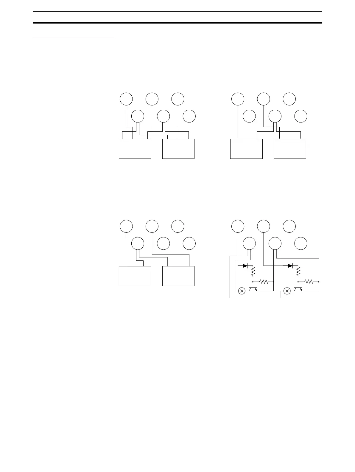
The following examples show various wiring possibilities for G72C Remote
Terminals.
A0 A1 A2
B0 B1 B2
+–+
–
– –
– – –
OUT
Three-wire
A0 A1 A2
B0 B1 B2
+–+
– – –
– – –
IN
Two-wire
Output –+–Output+
Sensor 1 Sensor 2
Output –+–Output+
Sensor 1 Sensor 2
When connecting outputs to logic external circuits, the external circuits must
be designed to be compatible with the output specifications of the Output Ter-
minal (pull-up resistance: 4.3 kΩ; residual voltage: 1.2 V).
A0 A1 A2
B0 B1 B2
Load
1 Load 2
+–+
– – –
– – –
OUT
Normal Loads
A0 A1 A2
B0 B1 B2
+–+
– – –
– – –
OUT
Logic Circuits
Input Terminals
Output Terminals
Wiring Section 5-5
Artisan Technology Group - Quality Instrumentation ... Guaranteed | (888) 88-SOURCE | www.artisantg.com
 Loading...