Appendix BSpecifications
146
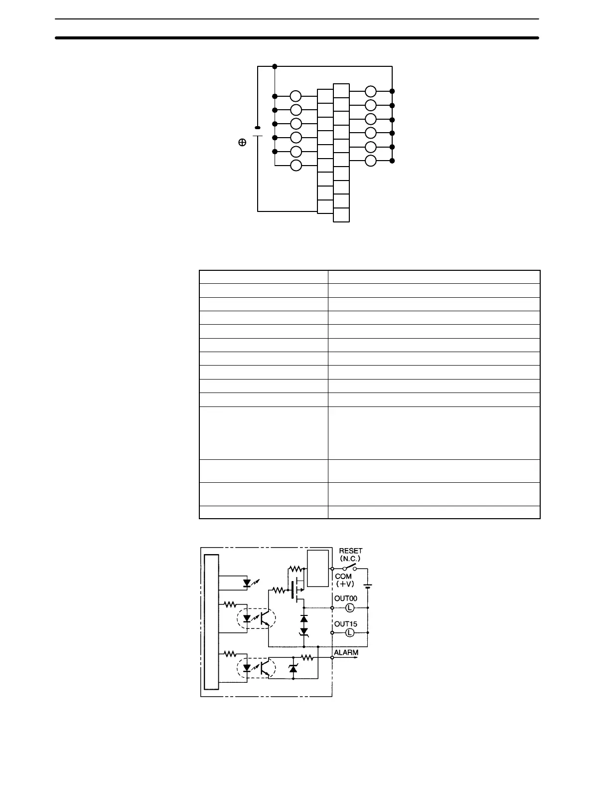
Terminal Connections
A0
A1
A2
A3
A4
A5
A6
A7
A8
1
3
5
7
9
11
COM
5 to 24 VDC
NC
B0
B1
B2
B3
B4
B5
B6
B7
B8
B9
NC
NC
NC
NC
NC
0
2
4
6
8
10
L
L
L
L
L
L
L
L
L
L
L
L
C200H-OD21A Transistor Output Unit (16 Points, Sourcing)
(Load Circuit Protection Provided)
Max. Switching Capacity 24 VDC
+10%
/
–15%
, 1.0 A (4 A/Unit)
Leakage Current 0.1 mA max.
Residual Voltage 0.8 V max.
ON Response Time 0.1 ms max.
OFF Response Time 0.3 ms max.
No. of Circuits 1 (16 points/common)
Internal Current Consumption 160 mA 5 VDC max.
Load Short-circuit Protection Detection current: 1.2 A min (1.6 A typical)
Power for External Supply 35 mA 24 VDC
+10%
/
–15%
min.
Weight 400 g max.
Alarm Output (See note 1.) No. of outputs: 1 (2 kΩ internal resistor)
Connectable Units: Only the following DC Input
Units can be connected:
C200H-ID001, ID211, ID212, IM211 (DC), IM212
(DC), ID215, ID501, MD115, MD215, MD501
Reset Input Used when alarm output turns ON. Value will
depend on the external power supply. (See note 2.)
Load Short-circuit Protection Detection current: 1.2 A min.
(1.6 A typical)
Dimensions B-shape
Circuit Configuration
Internal circuits
Output
indicator
0 V
2 kΩ
to
Short-circuit
protection
circuit
Note When short-circuit/overload protection is activated, all 16 outputs will be switched OFF and the ALARM
output becomes active (low level). The problem can be detected externally by connecting a DC Input Unit to