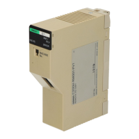
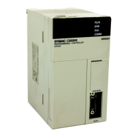
Do you have a question about the Omron C200HG-CPU43 and is the answer not in the manual?
Covers operating procedures, conditions, and consulting OMRON reps for specific applications.
Details critical safety warnings regarding power supply, terminals, and disassembly.
Lists locations to avoid for installation and necessary countermeasures.
Highlights precautions for grounding, power supply, voltage, and connections to prevent malfunction.
Explains how the PC controls manufacturing processes by accepting input and sending output signals.
Describes PC operation, internal logic, and the concept of cycle time for control.
Illustrates the basic PC configuration with CPU Rack, Expansion I/O Racks, and I/O Connecting Cables.
Describes various Units like CPU, Memory Cassettes, Communications Boards, and I/O Units.
Details configurations like Special I/O Units, Link Systems, and networks for system expansion.
Details necessary environmental conditions, precautions for static electricity, cooling, and spacing.
Covers power supply wiring, standard I/O unit wiring, and considerations for electrical noise.
Explains the console's nomenclature, mode selector, keys, and LCD area for program creation and monitoring.
Guides on verifying proper connection and initial operation of the PC and Programming Console.
Provides probable causes and possible corrections for errors in CPU Racks, Expansion I/O Racks, Input, and Output Units.
Details procedures for replacing fuses, relays, and batteries, and general inspection points.
Outlines daily and periodic inspection items, criteria, and required tools for maintaining PC condition.
Lists various Input, Output, Triac, Transistor, and Analog Timer Units with specifications and model numbers.
Lists High-density I/O Units, Analog I/O, Fuzzy Logic, Temperature Sensor, and Control Units with models.
Details Programming Consoles, Mounting Brackets, Connecting Cables, and Data Setting Consoles.
Provides detailed specifications for Power Supply Units including voltage, current, and resistance.
Details specifications for CPU Units including control methods, programming, execution time, and memory.
Specifies RS-232C port pin assignments, connections, applicable connectors, and port parameters.
Illustrates how to connect two CPU Units using the RS-232C port and provides grounding requirements.
Lists specifications for DC, AC, AC/DC Input Units, and Contact, Triac, Transistor Output Units.
Details specifications for DC Input and Transistor Output Units in Group-2 High-density I/O category.
Provides specifications for the TTL I/O Unit C200H-MD501, including input/output and general parameters.
Details specifications for the 12 VDC Input/Transistor Output Unit C200H-MD115.
Provides specifications for the 24 VDC Input/Transistor Output Unit C200H-MD215.
Details specifications for the Interrupt Input Unit, including rated voltage, impedance, and response times.
Lists specifications for the Analog Timer Unit C200H-TM001, including oscillation method and timer points.
Provides specifications for B7A Interface Units, including I/O points, transmission method, and distance.
Lists Group-2 B7A Interface Units with their input/output points and models.
Provides tables for maximum current and power supplied by Power Supply Units and their conditions.
Demonstrates methods for calculating current and power consumption with examples for various Unit combinations.
Explains how to calculate power consumption for CPU Racks and other Racks based on Unit power requirements.
Details current drawn by DC, AC, AC/DC Input Units, and Contact, Transistor, Triac Output Units.
Lists current drawn by TTL Input, DC Input, TTL Output, Transistor Output, TTL I/O, High-speed Counter, Position Control, Analog Input/Output, Motion Control, Temperature Sensor, ASCII, Voice Output, and ID Sensor Units.
Provides dimensions for CPU Racks, Expansion I/O Racks, and considerations for Programming Console Adapters.
Lists dimensions (Width W) for CPU and I/O Backplanes.
Shows dimensions for various Power Supply Units.
Details panel cut dimensions and mounting bracket usage for the Programming Console.
Provides dimensions for 10-terminal (A-shape), 19-terminal (B-shape), and Extended B-shape I/O Units.
Illustrates dimensions of Fujitsu Connector and G79-C Connecting Cable with units mounted.
Provides mounting dimensions (A and W) for CPU and I/O Backplanes.
Defines a PC as a computer-like device controlling peripherals based on programming and input devices.
| Category | Controller |
|---|---|
| Manufacturer | Omron |
| Model | C200HG-CPU43 |
| Operating Temperature | 0 to 55 °C |
| Max. Mounting Racks | 3 |
| Built-in RS-232C Port | Yes |
| Storage Temperature | -25 to 65°C |
| Type | Programmable Logic Controller (PLC) |
| CPU Model | C200HG |
| I/O Capacity | 512 points |
| Communication Ports | RS-232C |
| Power Supply | 24 VDC |
| I/O Points | 512 points |
| Instruction Execution Time (Basic Instructions) | 0.3 μs |
| Humidity | 10 to 90% RH (non-condensing) |
| Vibration Resistance | 10 to 57 Hz, 0.075 mm amplitude, 57 to 150 Hz, 1 G |


