30
Host Link Unit
connector pin no.
Direction of signalSymbolSignalHost Link Unit
connector pin no.
OutputInput
7 Signal ground SG (GND) --- ---
8 Detect carrier data CD (DCD) Yes No
14 5 V for optical
interface
5 V No Yes
20 Data terminal ready ER (DTR) No Yes
13
1
25
14
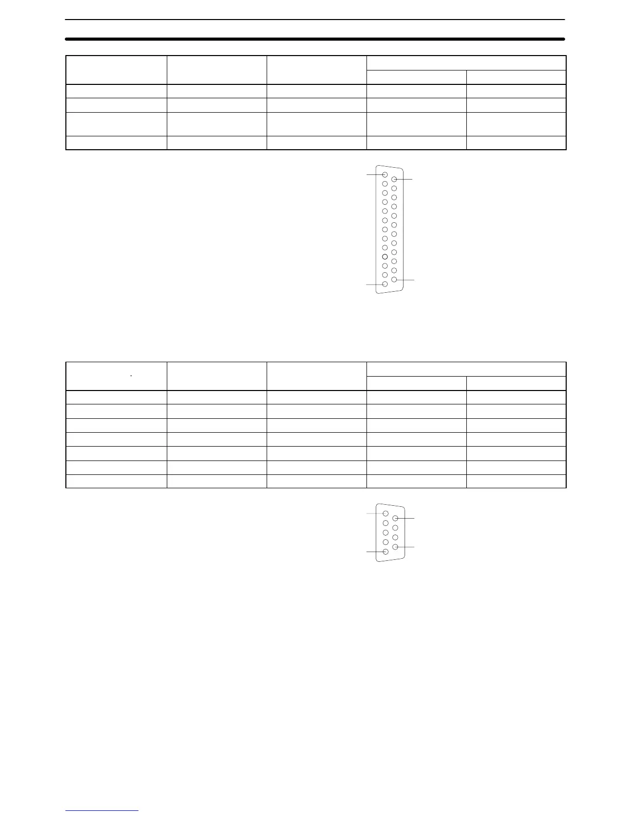
Communications Port 2 Electrical characteristics: Conforming to EIA RS-232C
Direction of signal: Viewed from the Host Link Unit.
Maximum cable length: 15 m
Host Link Unit
Signal Symbol Direction of signal
connector pin no.
Input Output
Connector hood Frame ground FG --- ---
2 Send data SD (TXD) No Yes
3 Receive data RD (RXD) Yes No
4 Request to send RS (RTS) No Yes
5 Clear to send CS (CTS) Yes No
7 Detect carrier data CD (DCD) Yes No
9 Signal ground SG (GND) No No
5
1
9
6
RS-232C Connections Section 3-4