I-70 Digital Controller E5CK
Installation
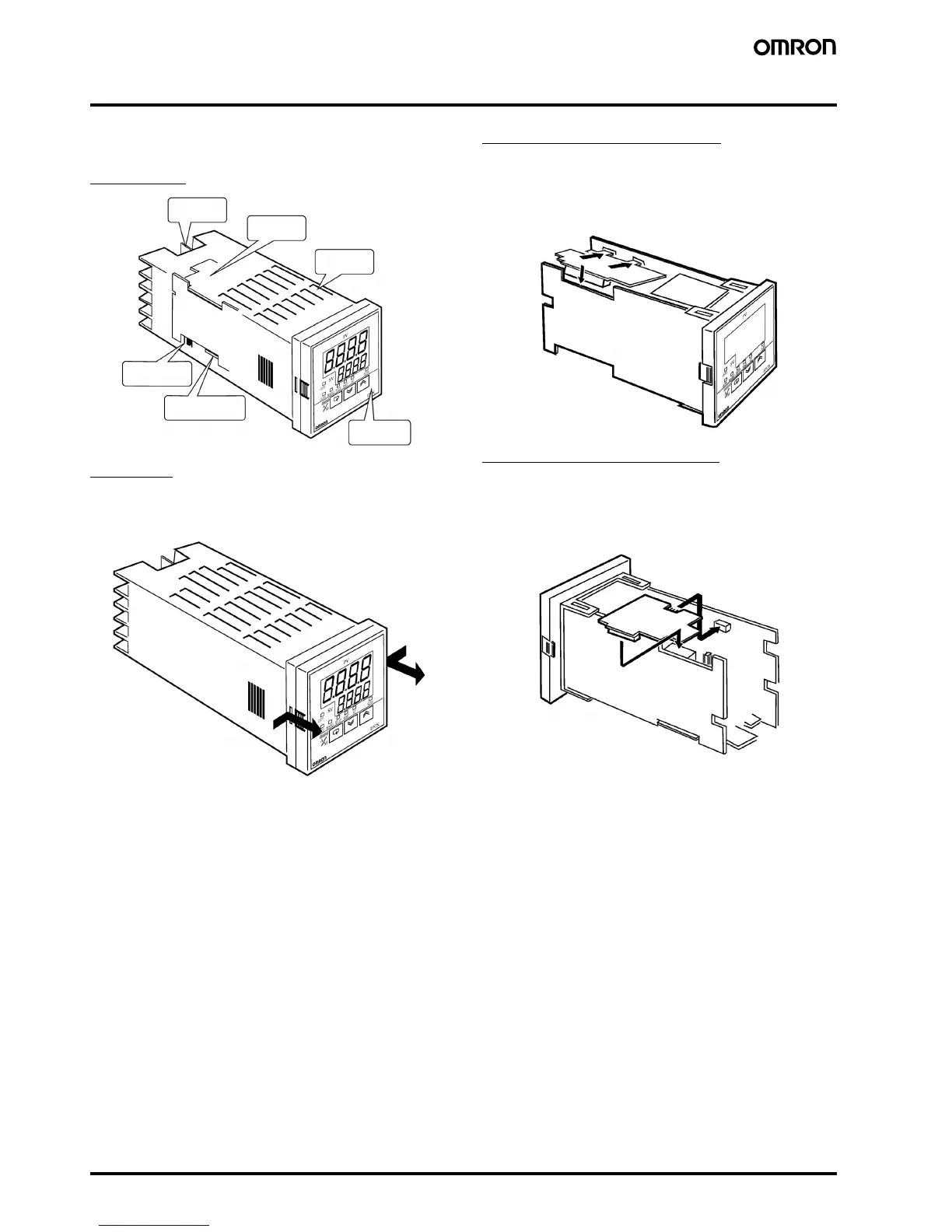
■ Installation
Main Parts
Draw-out
First, draw out the internal mechanism from the housing.
Pull out the internal mechanism while pressing the hooks on the left
and right sides of the front panel.
Setting Up the Output Unit
1. Two rectangular holes are provided on the power board (right side
of Controller). Fit the two protrusions of the Output Unit into these
two holes.
2. With the Output Unit fitted into the power board, fit the Output Unit
into the connector on the control board (left side of Controller).
Setting Up the Option Unit
1. Place the Controller with its bottom facing up, and fit the board
horizontally into the Connector on the power board (right side of
controller).
2. With the power board connected, fit the board vertically into the
Connector on the control board (left side of controller).
Terminals
Output Unit
Rear case
Front panel
Option Unit
Input type jump-
er connector
1
2
1
2

 Loading...