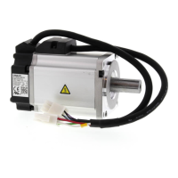
Do you have a question about the Omron R88M-K and is the answer not in the manual?
Details general specifications, characteristics, connector specifications, and I/O circuits of the Servo Drives.
Presents graphs showing load ratio and electronic thermal function's operation time for overload protection.
Details space conditions, mounting direction, and environmental conditions for Servo Drive and Servomotor installation.
Explains wiring procedures for power cables, peripheral equipment, and EtherCAT communications.
Describes operation where the controller provides target position via cyclic synchronization for precise positioning.
Explains operation where the controller provides target speed via cyclic synchronization for speed and torque control.
Details operation where the controller provides target torque via cyclic synchronization for torque control.
Covers PTP positioning operation, executing path generation, position, speed, and torque control.
Explains using an external encoder for direct position detection for highly accurate positioning.
Switches position loop and speed loop gain based on conditions like load inertia or speed.
Cuts off motor current via safety signals from a controller or sensor to stop the motor.
Describes objects specific to G5-series Servo Drives with built-in EtherCAT communications parameters.
Explains realtime autotuning and manual tuning methods for adjusting servo system gains.
Outlines the overall procedure from installation to operation, including checks and adjustments.
Explains procedures to prepare the mechanical system for operation and items to check before/after power ON.
Details inspections and procedures for confirming the servo system's electrical correctness.
Explains realtime autotuning and manual tuning methods for adjusting servo system gains.
Explains preliminary checks for problems, focusing on power supply and wiring.
Lists error codes, names, assumed causes, and measures for Servo Drive abnormalities.
Lists and describes error event codes from Sysmac Studio for G5-series Servo Drives.
| Type | AC Servo Motor |
|---|---|
| Series | R88M-K |
| Protection Class | IP65 |
| Rated Speed | 3000 rpm |
| Ambient Temperature | 0°C to 40°C |
| Vibration Resistance | 4.9 m/s² |


