Do you have a question about the Omron R88D-KN series and is the answer not in the manual?
Explains the target audience for this manual, focusing on individuals with electrical knowledge.
Contains important information for correctly using the Servo Drive and peripheral equipment.
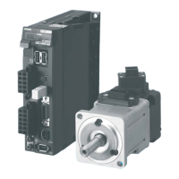
Provides an overview of the G5-series Servo Drives and their features.
Describes the overall system configuration for the G5-series AC Servo Drive with EtherCAT.
Details the part names and functions of the Servo Drive.
Illustrates the internal structure and connections of the G5-series AC Servo Drive.
Explains the typical system configurations when using the G5-series Servo Drives.
Provides guidance on interpreting the model numbers of the Servo Drives.
Lists the standard models for Servo Drives and related peripheral equipment.
Provides external and mounting dimension drawings for Servo Drives and peripheral devices.
Details general specifications, characteristics, and connector specifications for the Servo Drive.
Explains the overload protection function and its characteristics for the Servo Drive.
Provides specifications for various cables and connectors used with Servo Drives.
Details the specifications of external regeneration resistors used for energy absorption.
Lists the specifications for reactors used to suppress harmonic currents.
Describes the required environmental and space conditions for installing the Servo Drive.
Provides information on power supply, main circuit, and terminal block wiring for Servo Drives.
Explains wiring methods to ensure compliance with EMC directives.
Details how the Servo Drive absorbs regenerative energy and the role of regeneration resistors.
Explains the display area and how to set the EtherCAT node address.
Describes the structure of the CAN application protocol used for EtherCAT communications.
Explains the EtherCAT State Machine (ESM) and its control by the EtherCAT Master.
Details how process data objects (PDOs) are used for transferring data during cyclic communications.
Explains the use of SDO communications for setting objects and monitoring status.
Describes the use of distributed clocks (DC) for synchronizing EtherCAT communications.
Explains how emergency messages are sent to the master using mailbox communications.
Describes the features of the G5-series Servo Drive when combined with an OMRON Machine Automation Controller.
Explains the operation of the controller and Servo Drive in this mode for PTP positioning.
Details the operation where the controller provides target speed to the Servo Drive via cyclic synchronization.
Explains the operation where the controller provides target torque (force) to the Servo Drive via cyclic synchronization.
Describes how the Servo Drive performs PTP positioning using path generation and control based on target position.
Explains how the Servo Drive executes homing operations using methods specified by the controller.
Details the settings required to connect the Servo Drive with OMRON controllers via EtherCAT.
Explains how to set sequences in various operating conditions and allocate input/output functions.
Details how to prevent motor movement outside the allowable range using limit inputs.
Detects Overrun Limit Error and stops the Linear Motor if it exceeds the allowable operating range.
Explains how the function compensates for backlash in position control, though it's not applicable to Linear Motors.
Sets output timing for the brake interlock output (BKIR) that activates the holding brake.
Controls position by multiplying the position command by a preset electronic gear ratio.
Switches force limit based on movement direction and inputs, useful for push-motion operation.
Controls speed by setting acceleration/deceleration against the speed command, allowing soft starts.
Enables switching of position, speed, and force control gains based on various conditions.
Adds a new gain setting (gain 3) to the gain switching function for improved positioning stabilization.
Latches position actual value when an external latch signal or encoder's phase-Z signal turns ON.
Cuts off motor current and stops the motor using input signals from a safety device.
Provides timing charts illustrating the operation timings to enter and return from a safety status.
Shows example connection diagrams for safety devices like safety controllers.
Describes objects specific to G5-series Servo Drives with built-in EtherCAT communications.
Explains functions, setting methods, and notes for various gain adjustments.
Details settings for adaptive filter and notch filters to reduce resonance and vibration.
Explains how to control speed by setting acceleration/deceleration against the speed command.
Describes how to set analog monitor output voltage and scaling.
Describes objects related to positive/negative drive prohibition input and stop selection.
Covers objects like excessive speed error setting, gain switching, and force command offsets.
Details objects specific to the Linear Motor, such as resolution, pole pitch, and rated force.
Explains the overall procedure for checking motor and drive operation after installation and wiring.
Details essential checks before and after turning ON the power supply for mechanical system operation.
Outlines the steps for performing trial operation to confirm servo system correctness.
Explains the two types of analog signals that can be output from the analog monitor connector for adjustment.
Covers automatic and manual tuning methods to adjust servo gains for optimal performance.
Explains the realtime autotuning function for estimating load characteristics and automatically setting optimal gains.
Describes how to perform manual tuning when realtime autotuning cannot adjust gain properly due to load conditions.
Explains how to use damping control to reduce vibration in systems with low rigidity.
Details how the adaptive filter reduces resonance vibration by estimating resonance frequency.
Explains how notch filters can restrict resonance peaks and reduce vibration.
Describes how to use the disturbance force value estimated by the observer to reduce disturbance effects.
Explains two types of friction force compensation to reduce mechanical friction influences.
Covers speed feed-forward and force feed-forward for minimizing position error and improving responsiveness.
Explains how this function uses a load model to estimate motor speed for improved accuracy and reduced vibration.
Describes preliminary checks and precautions to take when a problem occurs.
Explains how the function outputs warning signals and notifies states like overload before errors occur.
Details the error codes output by the Servo Drive, their detection functions, and attributes.
Provides methods for determining error causes from displays and operating conditions.
Discusses the importance of periodic inspection and replacement for long-term operation.
Explains the profile used to control the Servo Drive, including state machines and modes of operation.
Explains the PDS state controlled by the Controlword and the Statusword displayed in each state.
Lists the supported modes of operation for G5-series Servo Drives with EtherCAT communications.
Describes modes of operation based on communication cycles and PDO mapping.
Shows the relationships between operational modes and applied functions.
Explains how to change the operational mode of the Servo Drive by setting the Modes of Operation object.
Details the homing methods supported by the G5-series AC Servo Drives.
Explains the structure of the object dictionary used for EtherCAT communications.
Describes objects related to EtherCAT communications, including device type and error registers.
Details the mapping of objects for receive and transmit PDOs, enabling data transfer.
Explains how Sync Manager communication objects are used for EtherCAT communications memory.
Describes objects specific to G5-series Servo Drives, including Sysmac error status and backup parameters.
Describes the CiA402 drive profile supported by G5-series Servo Drives, including Controlword and Statusword.
Provides a comprehensive list of objects, their properties, and default settings.
Lists and describes error event codes that may appear in Sysmac Studio, with assumed causes and remedies.
Lists and describes error event codes that may appear in Sysmac Studio, with assumed causes and remedies.
Provides detailed descriptions of various error codes, including meaning, assumed cause, and measures.
Lists and defines key terms used in EtherCAT communications for reference.
| Series | R88D-KN |
|---|---|
| Protection Class | IP20 |
| Communication | EtherCAT, MECHATROLINK-III |
| Ambient Temperature | 0°C to 55°C |
| Storage Temperature | -20°C to 85°C |
| Vibration Resistance | 4.9 m/s² |