E5AK/E5CK/E5EK
E5AK/E5CK/E5EK
103
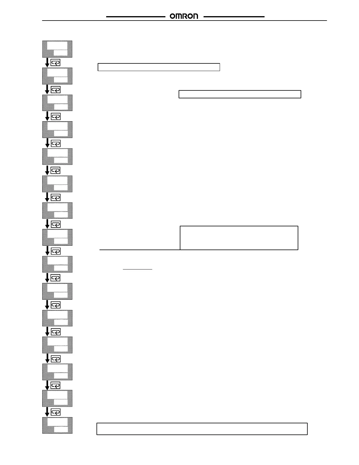
Level 1 Mode
off
a t
0
s p - 0
0
0
0
10.0
p
233
i
d
40
1.00
0.0
c - d b
50.0
h y s
0.10
0.10
s p - 1
a l - 1
a l - 2
c - s c
o f - r
c h y s
20
c p
20
c - c p
Control Period (Cool)
Available when the Controller has a relay or voltage output, or is in advanced PID control in heating and cooling
control.
Range = 1 to 99 s. Default = 20 s.
Control Period (Heat)
Available only when the Controller has a relay or voltage output, or is in advanced PID control.
Range = 1 to 99 s. Default = 20 s.
Hysteresis (Cool)
Available when the Controller is in ON/OFF control in heating and cooling control.
Range = 0.01 to 99.99 FS. Default = 0.10.
Hysteresis (Heat)
Available when the Controller is in ON/OFF control.
If PID control selected, this value will not appear on the menu.
Range = 0.01 to 99.99 FS. Default = 0.10.
Manual Reset Value
Available ONLY when the integral time parameter of the Controller in standard control is set to 0.
The Controller must be in Standard or Advanced PID control and self-tune must be set to off.
Dead Band
Used when the Controller is in heating and cooling control. This setting determines the amount of overlap or dead
band present in a heat/cool configuration. Range = -19.99 → 99.99.
Negative values = overlap band. Positive values = Dead band.
Cooling Coefficient
Used when the Controller is in heat/cool control. This setting describes the ratio between the heating proportional
band and the cooling proportional band.
c - s c = cooling P band
heating P band
Derivative Time
Range = 0 to 3999 seconds
See Note at right.
Integral Time
Range = 0 to 3999 seconds
Proportional Band
Range = 0.1% to 999.9%
Alarm Value 2
Available only when the alarm output function of the Controller is selected. This setting determines what the Alarm
2 set point will be. This alarm can be programmed to work on Control Output 2 or the SUB-1 output (user-select-
able). Factory Default = Control Output 2.
Note
: Alarm Value 3 is available only when SUB-1 or Control Output No. 1 is selected as AL-3.
Alarm Value 1
Available only when Control Output 2 is not used as a control output. This setting determines what the Alarm 1 set
point will be.
Set Point 1
Used only with multi-SP function. This set point is active when the Event input is ON.
This parameter is available only if an Event Input Option Board is installed.
Set Point 0
Default set point when used with multi-SP function. This set point is active when the Event input is OFF.
AT Execute/Cancel
Starts the Auto-tune function or cancels an active auto-tune. When an active auto-tune is cancelled, the original
PID constants will be used again.
AT-1 = Limited MV change during Autotuning (±40% max.)
AT-2 = Full MV change during Autotuning (±100% max.)
Note: This level 1 Mode ends here for the E5CK models only. For all other E5K models in this data sheet,
continue with the next page.
Note: For Valve Positioning Models E5K–PRR2, all
subsequent parameters (those after Derivative Time)
listed in Level 1 Mode are not available. See Level 1
Valve Positioning model (provided on the following
page).
Note: E5AK and E5EK can have up to 4 set points or 4 alarms
Note: E5AK and E5EK can have up to 4 set points or 4 alarms
Artisan Technology Group - Quality Instrumentation ... Guaranteed | (888) 88-SOURCE | www.artisantg.com

 Loading...