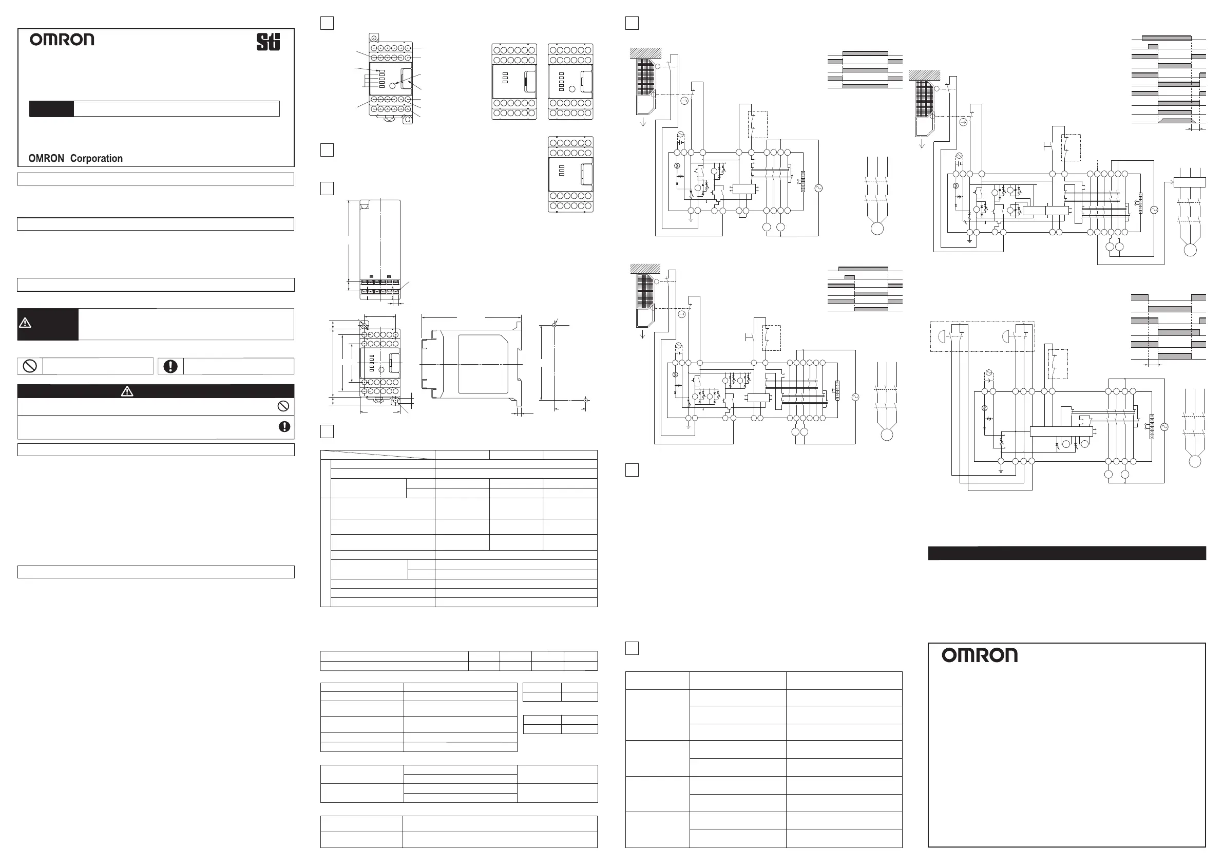
Designation
1
Internal connection
Application examples
2
External Physical Dimensions
3
5
Output terminals
Power input terminal
Output terminals
Power input terminal
OFF-delay time
setting switch
(Only for G9SA-321-T□)
Earth terminal
Refer to the product marking.
I/O terminals
Input power
indicator
Relay operation
indicator
6
Type G9SA can construct the condition conforming to PL=e and category 4 requested with by EN
ISO13849-1 European standard. (The part of off-delay output of G9SA-321-T□ can construct PL=d
and category 3.) This category class is recognised and based on the circuits we made, so we
would like you to conform the category class with G9SA at your application once. Category is
judged by the condition of the whole control system.
・ A condition for calculation of performance level (ENISO13849-1)
- Category 4 (The part of off-delay output of G9SA-321-T□: Category 3)
- DCavg: High (The part of off-delay output of G9SA-321-T□: Low)
- CCF: Min 65 points
- MTTFd:
G9SA-301:113 years, G9SA-501: 37 years, G9SA-321-T□: 32 years, G9SA-TH301: 86 years
* MTTFd is a value calculated based on the following operation conditions.
- Nop=31,680 cycles/year (dop=220 days/year、 hop=12 hours/day、 t cycle=300 seconds/cycle)
・ In order to be category 4 (EN ISO13849-1)
1. 2 channels are needed to external input at T11-T12, T21-T22.
2. The switch at T11-T12, T21-T22 should be constructed with positive open form. In case of
using limit switch, another one is requested positive open construction type.
3. The NC contact from a contactor is require to feed back signal T31-T32.
(Refer to the application examples.)
4. PE terminal should be dropped to earth.
5. Automatically start (Auto-reset mode) must be prevented through the superordinate control.
Failure detection
7
K1(K3) and K2(K4)
LED do not turn on.
Failures of the parts
of the internal circuits
Replace with a new product.
Failures involving the wiring of
External input (input line)
Failure indication
by LED
Failure condition
K1(K3) or K2(K4)
LED does not turn
on.
Power LED
does not turn on.
Type G9SA can detect the failure for the safety of internal circuit, parts condition and external
wiring.
(1) When ready for wiring, the power source should be disconnected first. Further, at operating this unit, the
terminal cover should be closed correctly in order to prevent an electrical shock.
(2) Do not wire in case threat of Lightning. otherwise an electric shock may occur.
(3) Do not apply any excessive voltage or current to the input or output circuit the G9SA. Doing so may result in
damage to the G9SA or cause a fire.
(4) Do not apply any variable voltage, otherwise G9SA may malfunction.
(5) Do not connect any overload to the output circuit, otherwise the G9SA in operation will generate excessive
heat and the output elements of the G9SA may short-circuit or fire may result.
(6) The lifetime of G9SA depends on the conditions of switching of its outputs. Be sure to conduct its test
operation under actual operating conditions in advance and use it within appropriate switching cycles.
Change the G9SA before expected operation. Over operation may cause may short-circuit or may
malfunction.
(7) Do not operate the G9SA with flammable or explosive gass. An arc with operation and the heat of relay will
cause a fire or an explosion.
(8) Do not disassemble, repair, or modify the G9SA, otherwise an electric shock may occur or the G9SA may
malfunction.
(9) Use protective device (Fuse of 5A current rating etc) for short-circuit protection and ground fault protection,
otherwise a fire may occur or the G9SA may malfunction.
Precautions for Safe Use
(1) For malfunctions in case that the power supply picks up gradually.
Malfunctions in case that the power supply picks up gradually. In case that the input circuits close before the
power supplies, internal logic may malfunction.
(2) Handling
1. Do not drop the G9SA or shock or vibrate the G9SA excessively. Doing so may result in damage to the
G9SA or cause G9SA to malfunction.
2. Do not turn the off-delay setting volume switch of G9SA-321-T□ less than the MIN value or more than
the MAX value. Otherwise the G9SA may be failed.
(3) For adhesion of solvent
Adhesion of solvent, likely Alcohol, Thinner, Trichloroethane, Gasoline, on the product should be prohibited.
Such solvent cause erasing the marking and being inferior of the parts.
(4) Operating and Storage Environment
Do not operate or store the G9SA under the following conditions.
Doing so may result in damage to the G9SA or cause the G9SA to malfunction.
1. The places with direct sunlight.
2. The places with ambient temperature ranges not within -25 to 55℃.
3. The places with rapid temperature changes resulting in condensation or relative humidity ranges not
within 35 to 85%RH.
4. The places with atmospheric pressure out of the range 86 to 106kpa.
5. The places with corrosive or inflammable gas.
6. The places with water, oil, or chemical sprayed on the G9SA.
7. The places with vibration or shock affecting the G9SA.
8. The places with atmosphere containing dusts, saline or metal powder.
(5) Mounting multiple units
When mounting multiple units close to each other, the rated current will be 3A. Do not apply a current
higher than 3A.
(6) For feedback purpose use devices with contacts capable of switching micro loads of 24VDC, 5mA.
(7) The Safety input OFF signal for T11/T12 (or T23) and T21/T22 terminals must be longer than the response
time (10ms). Otherwise, the G9SA will be locked out or will not be able to be started or restarted.
Also, a shorter safety input OFF signal might cause the G9SA to be locked. In this case, all safety inputs
must be turned off or the power supply for G9SA must be off before restarting the G9SA.
(8) Wiring
1. Use the following to wire the G9SA.
- Stranded wire (Flexible wire): 0.75 to 1.5mm
2
- Solid wire: 1.0 to 1.5mm
2
2. The G9SA may malfunction or generate heat.
- Tighten each screw to a torque of 0.78 to 1.18N・m,
3. External inputs connected to T11 and T12 or T21 and T22 of the G9SA must be no-voltage contact inputs.
4. PE is a ground terminal. When machine is grounded at the positive, the PE terminal should not be
grounded.
(9) This is a class A product. In residential areas it may cause radio interference, in which case the user may be
required to take adequate measures to reduce interference.
(10) Mounting Expansion units
When an Expansion Unit is being used, remove the connector cover from the G9SA Master Units and insert
the connector of the Expansion Unit's connector cable. Make sure that the connector is correctly locked
before operating.
Precautions for Correct Use
Aug. 2010
Thank you for purchasing G9SA Safety Relay Unit.
Please read and understand this manual before using the products.
Keep this manual ready to use whenever needed.
Only qualified person trained in professional electrical technique should handle G9SA.
Please consult your OMRON representative if you have any questions or comments.
Make sure that information written in this document are delivered to the final user of the product.
USER'S MANUAL
Type G9SA-301
Safety Relay Unit
Type G9SA-501
Type G9SA-321-T□
Type G9SA-TH301
24VAC/DC
Specifications
4
Type for G9SA-321-T□
-T015
1.5s 7.5s
15s
30s
MAX. Off-delay time / 15 steps
● Off-delay time
-T075
-T15
-T30
● Characteristics
Operating time
30ms MAX.
10 to 55Hz 0.375mm single amplitude
(0.75mm double amplitude)
Destruction: 300m/s
2
Malfunction: 100m/s
2
Ambient humidity
Ambient temperature
Shock resistance
Vibration resistance
Response time
35 to 85%RH
-25 to 55℃
10ms MAX.
● Protection class
IP20
Enclosure
Terminals
IP40
G9SA-301: Twenty, M3
G9SA-501: Twenty-four, M3
G9SA-321-T□: Twenty-four, M3
G9SA-TH301: Twenty-one, M3
111 MAX.
Type G9SA-301
Type G9SA-501
Type G9SA-321-T□
Type G9SA-TH301
4363
76 MAX.
9
7×5=35
45 MAX.
R2.3
5.6
9
4.6 dia.
35±0.3
84
±0.3
Two, 4.2 dia. or M4
● G9SA-301 Limit Switch Input 2ch / Auto-reset
open
S1
S2
23
24
11
12
KM1
KM2
KM1
KM2
Feedback loop
M
KM1
KM2
A1
A2
T12
T11
T31
T32
13
23
33
41
14
24
34
42
A
B
T21
T22
PE
T23
K1
K2
a
b
a
b
K1
K2
K1
K2
2
5
6
1
3
4
TH
SA
1
2
3
4
5
6
JP
● G9SA-501 Limit Switch Input 2ch / Manual-reset
S1
11
12
KM1
KM2
S3
KM1
KM2
M
S2
23
24
KM1
KM2
open
A1
A2
T12
T11
T31
T32
A
B
T22
PE
T23
K1
K2
a
b
a
b
K1
K2
K3
K4
2
5
6
1
3
4
Control
Circuit
K3
K4
K1
K2
13
23
33
43
14
24
34
44
53
61
54
62
TH
SA
T21
Feedback loop
1
2
3
4
5
6
JP
● G9SA-321-T□ Limit Switch Input 2ch / Manual-reset
S1
11
12
KM1
KM2
Feedback loop
S3
S2
23
24
KM1
KM2
open
KM1
KM2
M
Motor
Controller
A1
A2
T12
T11
A
B
T21
T22
PE
T23
13
23
33
43
14
24
34
44
53
61
54
62
K1
K2
a
b
a
b
K1
K2
K1
K2
6
1
3
4
Control
Circuit
K3
K4
K3
K4
Off Delay
Timer
2
5
T31
T32
TH
SA
Operation instruction
1
2
3
4
5
6
JP
● G9SA-TH301 with 2-hand Input
S11
S12
KM1
KM2
KM1
KM2
Feedback loop
1
2
3
4
5
6
K1
K2
Control Circuit
6
1
3
4
2
5
K1
K2
TH
SA
JP
*1) Safety outputs *2) Non-safety outputs
*3) When the inputs of G9SA-321-T□ are restored during off-delay time,
G9SA-321-T□ will operate as below. depending on the reset mode.
- Auto reset mode: Outputs turn off after off-delay time, then immediately turns on.
- Manual reset mode: Outputs turn off after off-delay time, then turn on when reset input is given.
24VDC
AC15
DC13
1.7W MAX. 2.6W MAX. 3.3W MAX.
250VAC 5A cosφ=1 30VDC 5A L/R=0ms
240VAC 2A cosφ=0.3
24VDC 1A L/R=48ms
5A (1 Output)
IEC60947-5-1
Table 4
● Ratings
Rated carry current
Max. switching voltage
Rated load
Rated power
consumption
24VAC
1.8VA MAX.
2.8VA MAX.
3.5VA MAX.
250VAC 125VDC
G9SA-301/TH301 G9SA-501 G9SA-321-T□
13/14,23/24,33/34
41/42
61/6261/62
13/14,23/24,33/34
43/44,53/54
13/14,23/24,33/34
43/44,53/54
N.O. contacts *1)
3 N.O.
---
---
1 N.C.
1 N.C. 1 N.C.
3 N.O.
2 N.O.
5 N.O.
Off-delay contacts *1) *3)
N.C. contacts *2)
Auxiliary contacts
English
13 23 33 41
14 24 34 42
T11 T12 T31 T32 T23
A1
T21 T22
A B PE A2
13 23 33 41
14 24 34 42
T11 T12 T13 T31 T32
A1
T21 T22 T23
PE A2
13 23 33 43 53 61
14 24 34 44 54 62
T11 T12 T31 T32 T23
A1
T21 T22
A B PE A2
I/O terminals
5.9
10.5
91
Rated supply voltage
Operating voltage range
24VAC / 24VDC
-15% to +10% of rated supply voltage
InputOutput
● Pollution degree
3
2
External
Internal
Checking points and measures
to take
Failures involving the wiring of
External input (input line)
Failures of the parts of the
External devices (Contactor etc)
Failures of the parts
of the internal circuits
Replace with a new External devices.
(Contactor etc)
Failures of the parts
of the internal circuits
Replace with a new product.
Supply voltage outside
the rated value
Check the supply voltage to
Expansion.
Failures involving the wiring of
External input (output line)
Replace with a new product.
Check the wiring to External input.
(input line)
Check the wiring to External input.
(output line)
Check the wiring to External input.
(input line)
Failures of the parts of the
Protective device (Fuse etc)
Replace with a new Protective device.
(Fuse etc)
All LED turn on.
but the safety
output doesn't on.
Control
Circuit
T13
T11
T12
A1
A2
T31
T32
13
33
41
23
14
24
34
42
T21
T22
PE
T23
WARNING
Precaution for Safe Use
Indicates a potentially hazardous situation which, if not
avoided, will result in minor or moderate injury, or may
result in serious injury or death.
Additionally there may be significant property damage.
Meanings of Signal Words
The following signal words are used in this manual.
Meaning of Alert Symbols
The following alert symbols are used in this manual.
Serious injury may possibly occur due to breakdown of safety outputs.
Do not connect loads beyond the rated value tothe safety outputs.
Serious injury may possibly occur due to loss of required safety functions.
Wire G9SA properly so that supply voltages or voltages for loads do NOT
touch the safety inputs accidentally or unintentionally.
WARNING
Alert Statements
Indicates prohibited actions
Indicates mandatory actions
Mounting holes
EU Declaration of Conformity
Standards
OMRON declares that G9SA series are in conformity with the requirements of
the following EU Directives:
- EMC Directive: 2004/108/EC
- Machinery Directive: 2006/42/EC
G9SA series are designed and manufactured in accordance with the following
standards:
- EN ISO13849-1: 2008 PL e Category 4
- EN 574: 1996/A1: 2008 (G9SA-TH301 only)
- EN 60947-5-1: 2004
- UL508, CAN/CSA C22.2 No.14
KM1
KM2
M
Original instructions
● Life expectancy
Electrical endurance
Mechanical endurance
100,000 operations MIN. Rated load
Switching frequency 1,800 operations/h
5,000,000 operations MIN.
Switching frequency 7,200 operations/h
Insulation resistance
Dielectric strength
Between different poles of output
● Isolation specification
Between different poles of output
Between inputs and outputs
Between inputs and outputs
100Mohm MIN.
(by 500VDC Megger)
2,500VAC 1min.
Connector cover
5
OMRON shall not be responsible for conformity with any standards, codes, or
regulations that apply to the combination of the products in the customer's
application or use of the product.
Take all necessary steps to determine the suitability of the product for the
systems, machines, and equipment with which it will be used. Know and
observe all prohibitions of use applicable to this product.
NEVER USE THE PRODUCTS FOR AN APPLICATION INVOLVING SERIOUS RISK
TO LIFE OR PROPERTY WITHOUT ENSURING THAT THE SYSTEM AS A WHOLE
HAS BEEN DESIGNED TO ADDRESS THE RISKS, AND THAT THE OMRON
PRODUCT IS PROPERLY RATED AND INSTALLED FOR THE INTENDED USE
WITHIN THE OVERALL EQUIPMENT OR SYSTEM.
Suitability for Use
OMRON EUROPE B.V. (Importer in EU)
Wegalaan 67-69, NL-2132 JD Hoofddorp
THE NETHERLANDS
PHONE 31-2356-81-300 FAX 31-2356-81-388
2895 Greenspoint Parkway, Suite 200
Hoffman Estates, IL 60169 U.S.A.
Tel: (1) 847-843-7900/Fax: (1) 847-843-7787
OMRON ASIA PACIFIC PTE. LTD.
438A Alexandra Road # 05-05/08,
Alexandra Technopark Singapore 119967
SINGAPORE
PHONE 65-6-835-3011 FAX 65-6-835-2711
Note: Specifications subject to change without notice.
OMRON Corporation (Manufacturer)
Shiokoji Horikawa, Shimogyo-ku, Kyoto, 600-8530
JAPAN
OMRON (CHINA) CO., LTD.
Room 2211, Bank of China Tower, 200 Yin Cheng Zhong Road,
PuDong New Area, Shanghai, 200120, China
PHONE 86-21-5037-2222 / FAX 86-21-5037-2200
For performance level safety category (EN ISO13849-1)
Limit switches S1 and S2
K1,K2,K3,K4 (NC)
K1,K2,K3,K4 (NO)
KM1,KM2 (NC)
KM1,KM2 (NO)
Reset switch S3
Limit switches S1 and S2
Reset switch S3
Operation instruction
K1,K2 (NC)
K1,K2 (NO)
K3,K4 (NC)
K3,K4 (NO)
KM1,KM2 (NC)
KM1,KM2 (NO)
Motor rotation
OFF-delay time
S11 (NO)
S11 (NC)
S12 (NC)
S12 (NO)
KM1,KM2 (NC)
KM1,KM2 (NO)
MAX. 0.5s
K1,K2 (S)
K1,K2 (ö)
KM1,KM2 (ö)
KM1,KM2 (S)
Positionsschalter S1 und S2
1,000A
Rated conditional short-circuit current
0622108-9J
OMRON ELECTRONICS LLC
 Loading...