G9SA
4
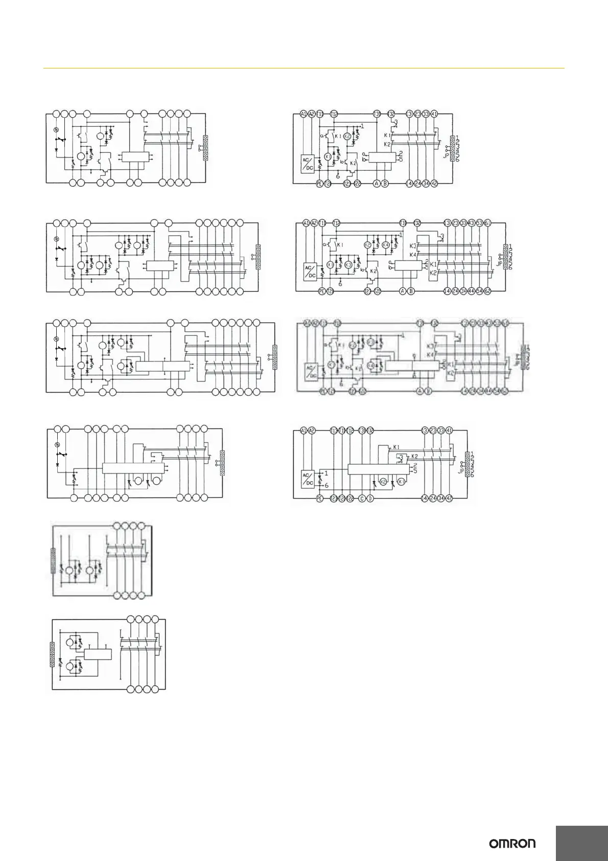
Connections
Internal Connections
A1 A2
T11
T12 T31
T32
13 23 33 41
1
2
3
4
5
6
K1
K1
K2
2
5
a
6
b
a
b
K2
3
4
K1
K2
1
JP
PE
T21
T23
T22
AB
14 24 34 42
13 23 33 43 53 61
T31 T32
A1 A2
T11 T12
K2
K1
K3
K4
K2
b
K1
a
6
a
b
K2
K1
2
5
K3
K4
3
4
1
2
3
4
5
6
JP
PE
T21 T23 T22
AB
14 24 34 44 54 62
13 23 33 41
12 5 4
K1
K2
36
14 24 34 42
K1 K2
1
2
3
4
5
6
A1 A2
T11 T12
K1
a
K2
K4
1
K3
K4
3
4
2
5
K2
K1
14 24 34 44 54 62
AB
PE
T21
T23
T22
6
b
K2
K3
K1
a
b
1
2
3
4
5
6
JP
T31 T32
13 23 33 43 53 61
A1 A2
T11 T12 T31 T32T13
13 23 33 41
1
2
3
4
5
6
JP
14 24 34 42
K1
K2
1
6
2
5
K2
3
4
K1
PE
T23 T21 T22
CD
2
5
K1
K2
4
1
6
3
K2
K1
1
2
3
4
5
6
13 23 33 41
14
24
34
42
G9SA-301 (24 VAC/VDC)
G9SA-501 (24 VAC/VDC)
G9SA-321-T@ (24 VAC/VDC)
G9SA-TH301 (24 VAC/VDC)
G9SA-EX301
G9SA-EX031-T@
Control circuit
G9SA-301 (100 to 240 VAC)
G9SA-501 (100 to 240 VAC)
G9SA-321-T@ (100 to 240 VAC)
G9SA-TH301 (100 to 240 VAC)
*2 *
1
*2 *1
*2 *1 *3
*2 *1
*2 *1
*2
*1 *3
Control circuit
Control
circuit
Control
circuit
Control
circuit
Control
circuit
Off delay
timer
Control
circuit
Off delay
timer
Control
circuit
Off delay
timer
TH
SA
TH
SA
TH
SA
TH
SA
Note: 1. With 100 to 240-VAC type, be sure to connect PE to a protective
ground. With 24-VAC/VDC type, if the power supply is not
connected to a protective ground, be sure to connect PE to a
protective ground.
2. With 24-VAC/VDC type, the power supply terminals A1 and A2
have polarities. A2 is the negative pole.
*1. Use terminals A and B to switch reset mode.
A to B open: Manual reset
A to B closed: Auto-reset
*2. Terminal T23 is used for 2-channel input with a positive common
(when connecting a safety sensor with a PNP output).
When using T23, make sure that T21 and T22 are open.
For 1-channel input, make sure that T12 and T23 are shorted.
*3. Terminals 43-44 and terminals 53-54 are OFF-delayed outputs.