Do you have a question about the Omron H3BA-N and is the answer not in the manual?
Overview of the H3BA-N, a multi-functional timer with various operating modes.
Introduction to the H3BF-N, a timer designed for twin timing applications.
Details the H3BG-N, a timer specifically for star-delta motor starting.
Description of the H3BH-N, a timer that operates on power OFF delay.
Explains the coding system used for H3BA-N model numbers.
Catalog of H3BA-N timer models, categorized by output and supply voltage.
Lists optional accessories that can be ordered separately.
Details operating modes, pin/input/output types, mounting, and approvals.
Covers available time units (sec, min, hrs) and setting range options.
Specifies supply voltage, operating range, power consumption, and output contact ratings.
Details accuracy, setting error, reset time, and voltage/temperature influence.
Covers insulation, dielectric strength, noise/static immunity, vibration, and shock resistance.
Specifies mechanical/electrical life, case color, enclosure ratings, and weight.
Internal functional block diagrams for H3BA-N and H3BA-N8H models.
Describes input signals (Start, Reset, Gate) and control output operation.
How to set operating mode, output type, time unit, and time range selectors.
Instructions for using the time setting knob to adjust the timer's duration.
Guide to using Time Setting Ring A for accurate time setting.
Using Time Setting Rings B/C to define time range limits.
Timing diagrams illustrating H3BA-N operating modes A, B, B2, and C.
Timing diagrams for H3BA-N modes D, E, and Gate Signal input operation.
Timing charts for H3BA-N8H with Type A and Type H output configurations.
Overall dimensions for H3BA-N and H3BA-N8H timer units.
Dimensions illustrating use with set rings and flush mounting adapters.
Dimensions for Y92F-70 and Y92F-71 flush mounting adapters.
Dimensions for track mounting and flush mounting socket configurations.
Details P2CF (front) and P3G (back) connecting sockets for mounting.
Information on PFP series mounting tracks for DIN rail installation.
Includes end plates, spacers, protective covers, and panel covers.
Covers time setting rings and hold-down clips for improved usability.
Wiring diagrams showing terminal layouts for H3BA-N and H3BA-N8H models.
Explains no-contact and contact input wiring methods.
Defines signal levels and impedance for various input types.
Crucial safety advice regarding electric shock, burns, fires, and handling.
Guidance on setting changes, power connection, and input/output usage.
Tips on setting time, accuracy considerations, and model selection.
Covers dielectric testing, inductive loads, time-up conditions, and service life.
Details surface mounting and P2CF socket vertical mounting procedures.
Steps for PL socket securing and panel mounting with adapters.
Instructions for removing the timer from surface and panel mounts.
OMRON's warranty terms, liability limits, and disclaimers.
Guidance on product suitability, programmable products, and performance data.
The Omron H3BA-N Solid-state Timer is a versatile and reliable device designed for various industrial timing applications. It offers a broad lineup of models, including multi-functional, twin, star-delta, and power OFF-delay timers, catering to a wide range of control needs.
The H3BA-N series timers are primarily used for controlling the duration of events in automated systems. They operate by receiving an input signal and, after a set time, activating or deactivating an output. The multi-functional models, such as H3BA-N, provide a comprehensive set of operating modes, including ON-delay, flicker OFF start, flicker ON start, signal ON/OFF-delay, and interval. This flexibility allows them to be adapted to complex timing sequences.
The H3BA-N models typically feature a DPDT (time-limit) output, while the H3BA-N8H models offer a DPDT (time-limit) and switchable SPDT (time-limit <<>> instantaneous) output, providing additional control options. The twin timers (H3BF-N) are designed for applications requiring two independent timing functions, while star-delta timers (H3BG-N) are specifically tailored for motor starting applications, providing both time-limit and instantaneous contact outputs. Power OFF-delay timers (H3BH-N) maintain their output for a set duration after the power supply is removed, which is useful for applications requiring a controlled shutdown.
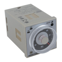
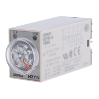
The timers are equipped with clear indicators for power ON and output ON status, allowing for easy monitoring of their operation. They also feature a time range/unit selector and an operating mode or output type selector, which are typically adjusted using a screwdriver. This design ensures that the timer's settings are not accidentally altered during operation.
The H3BA-N timers are designed for ease of use and installation. They can be mounted in various ways, including flush mounting to a panel, track mounting, or surface mounting. Flush mounting provides a clean and integrated look, while track mounting is convenient for systems using DIN rails. Panel covers and protective covers are available as accessories to enhance safety and prevent accidental changes to settings.
Setting the time is straightforward, typically involving a time setting knob. For models with multiple time ranges, a selector allows the user to choose the appropriate range (e.g., 1.2, 3, 12, or 30 seconds, minutes, or hours). The time setting knob then allows for fine-tuning within the selected range. Some models feature a setting ring that can be locked to prevent unauthorized adjustments.
The timers support various input types, including no-voltage inputs (from NPN open collector output sensors or contacts) and contact inputs. This broad compatibility allows them to be integrated into diverse control circuits. The input signals can be used for starting, resetting, or gating the timing operation, providing precise control over the timer's behavior.
For the H3BA-N8H models, the output type can be switched between time-limit DPDT and time-limit SPDT + instantaneous SPDT using a selector. This feature adds flexibility, allowing the timer to provide an immediate output in addition to the delayed output, which can be useful for interlocking or signaling purposes.
The panel covers, available in different colors (light gray, black, medium gray), not only protect the settings but also allow for customization to match the aesthetic of the control panel. Hold-down clips are also available to secure the timer in its socket, ensuring a stable connection even in environments with vibration.
The H3BA-N series timers are designed for durability and long-term reliability, minimizing the need for frequent maintenance. Their solid-state construction contributes to a longer operational life compared to mechanical timers, as there are no moving parts to wear out.
In the event of a malfunction or for routine checks, the timers are designed for relatively easy removal and replacement. For flush-mounted timers, the flush mounting adapter can be loosened to remove the timer from the panel. For socket-mounted timers, the timer can be simply pulled out from its socket after disengaging any hold-down clips.
When replacing a timer, it is important to ensure that the new timer has the correct specifications (e.g., supply voltage, output type) to match the application. The modular design, with separate sockets and mounting adapters, simplifies the replacement process, as the wiring can remain undisturbed while the timer unit itself is exchanged.
Regular visual inspections are recommended to check for any signs of damage, loose connections, or environmental factors that might affect performance, such as excessive dust or moisture. Keeping the timer and its surrounding area clean can help prevent issues.
The use of protective covers (Y92A-48B) helps to shield the front panel from dust, dirt, and accidental contact, which can extend the life of the setting components and maintain the timer's accuracy. These covers are typically made of hard plastic and can be easily attached or removed.
Overall, the Omron H3BA-N Solid-state Timer series offers a robust, flexible, and user-friendly solution for a wide array of timing control applications, with features that support both efficient operation and straightforward maintenance.
| Type | Digital Timer |
|---|---|
| Input Voltage | 100-240 VAC |
| Output Type | Relay |
| Supply Voltage | 100-240 VAC |
| Contact Output | SPDT |
| Number of Pins | 8 |
| Power Supply Voltage | 100-240 VAC |
| Mounting Type | DIN Rail |
| Operating Temperature | -10°C to 55°C |
| Storage Temperature | -25°C to 65°C (with no icing or condensation) |