H3T
H3T
149
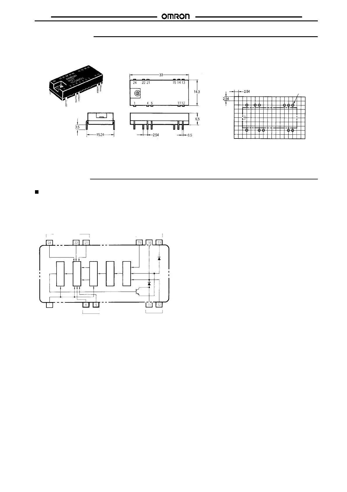
Dimensions
Note: All units are in millimeters unless otherwise indicated.
Note: 1. Terminal pitch: 2.54 mm
2. Conventionalmodelswithonlyasingletimerangedonot
have terminals 4 and 5.
PCB Dimensions
(Top View)
Applicable socket: XR2A-2401-N
H3T
Eleven, 1.0 dia.
Installation
Internal Connections
Whenthe input voltage is applied, the CR oscillator circuit in the timer receives current throughthe powercircuits andbegins oscillation. When
thevaluesetinthetimingcircuitiscounted, anoutputsignalis generated.Thissignalisamplifiedby atransistortooperatetheload.Thevoltage
created across the load is the input voltage minus the forward voltage drop of the transistor and diode.
Note: 1. A diode is connected internally to adsorb
surge voltage generated by the output relay.
2. Terminals 12 and 14 are internally connected.
3. There are no time range switching terminals
as there were on previous models.
(Top View)
Setting inputs
Power supply
Reset input Time range
switching
Control output
Rated voltage
Power circuit
CR oscillator
Timer circuit
Output
circuit
amplifier
(See note
1)