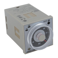
H3CR-A
H3CR-A
31
Input Connections
The inputs of the H3CR are no-voltage (short circuit or open) inputs.
No-voltage Input Signal Levels
No-contact
input
Contact
input
1. Short-circuit level
Transistor ON
Residual voltage: 1 V max.
Impedance when ON: 1 k
$
max.
2. Open level
Transistor OFF
Impedance when OFF: 100 k
$
min.
Use contacts which can adequate-
ly switch 80
&
Aat5V
No-contact Input
(Connection to NPN open
collector output sensor.)
Contact Input No-contact Input
(Connection to a voltage
output sensor.)
No-voltage inputs
12 to 24 VDC (sensor
power supply)
Sensor
Timer
Start/reset/
gate
Input (0 V)
(No. 2 pin)
Operates with transistor ON
+
--
DC power
supply
Timer
Start/reset/
gate
Input (0 V)
(No. 2 pin)
Operates with relay ON
12 to 24 VDC (sensor
power supply)
Sensor
Timer
Start/reset/
gate
Input (0 V)
(No. 2 pin)
Operates with transistor ON
+
--
DC power
supply
Application Examples
A Mode: ON-delay
ON-delay operation (A mode) is a basic mode.
1. Power-ON Start/Power-OFF Reset
ThePower-ONstart/Power-OFF resetoperationisastandardoper-
ating method.
Power (2 and 10)
Start (2 and 6)
Control output: NC (8 and 11)
NC (1 and 4)
Control output:NO (9 and 11)
NO (1 and 3)
Power indicator
Flashing Lit
t
Externally short-circuited
Power
supply
2. Signal Start/Signal Reset
TheSignalstart/Signalresetoperationisusefulforremotecontrolof
the Timer.
Power (2 and 10)
Start (2 and 6)
Control output: NC (8 and 11)
NC (1 and 4)
Control output: NO (9 and 11)
NO (1 and 3)
Power indicator
Flashing Lit
t
Reset (2 and 7)
(Power continuously supplied)
Start signal (remote control possible)
Reset signal
(remote control possible)
Power
supply