H3CA-A
3
1
6
2
4
5
9
8
7
Reset
Start
COM
11
10
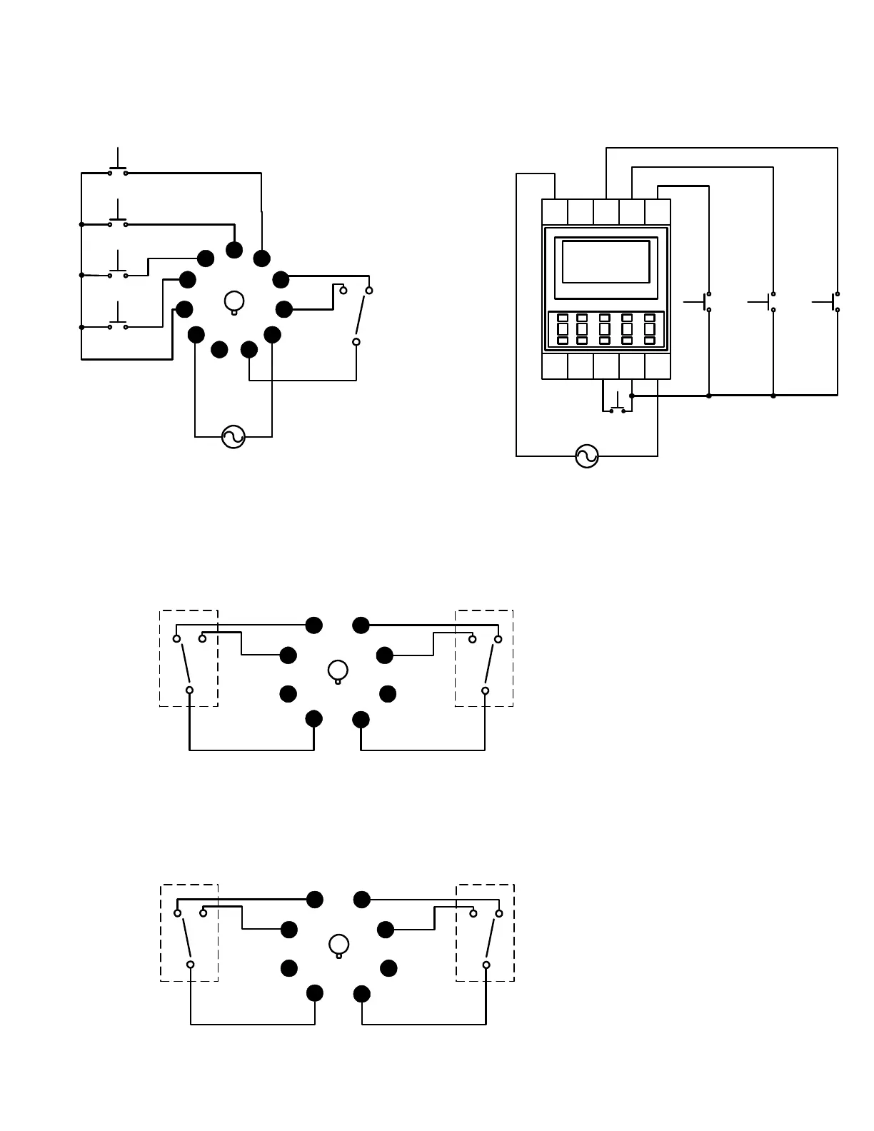
Supply voltage
can be either a
AC or DC source
Pins 8, 9, and 11 are
terminals for the timer's
internal output relay.
Pins 3 & 7 is the Reset Input
Pins 3 & 6 is the Start Input
Pins 3 & 5 is the Gate Input
Pins 3 & 4 is the Check Input
Gate
Check
Product Operation and Setup Instructions 1A983
Supply Voltage
A1
16 18 E1 X A2
15 D1 C1 B1
H3CA-FA
Check
Reset Start
Supply voltage
can be either a
AC or DC source
*Outputs: Pins 15, 16, and 18 are
the terminals for the timer's internal
output relay.
Pin 15 is the COM.
Pin 16 is the NC contact.
Pin 18 is the NO contact.
H3CA-8
1
2
3
4
7
6
5
8
Timed
contact
Timed
contact
H3CA-8H
1
2
3
4
7
6
5
8
Instantaneous
contact
Timed
contact
**
*
Terminal/Pin Configuration
Outputs: Pins 1,3,4,5,6, and 8 are the terminals for
the H3CA-8H internal output relays.
Relay #1: Is an instantaneous contact. Which means
this relay will immediately switch when power is apply
to timer.
Pin 1 is the COM for relay #1.
Pin 3 is the NO contact for relay #1.
Pin 4 is the NC contact for relay #2.
Relay #2: Is a timed contact. Which means this
relay will only switch at the end of the time delay
period.
Pin 8 is the COM for relay #2.
Pin 6 is the NO contact for relay #2.
Pin 5 is the NC contact for relay #2.
Because both internal relay outputs are totally
different in function. Please make sure not to wire
these relays together in an application.
Outputs: Pins 1,3,4,5,6, and 8 are the terminals for
the H3CA-8 internal output relays.
Pin 1 is the COM for relay #1.
Pin 3 is the NO contact for relay #1.
Pin 4 is the NC contact for relay #2.
Pin 8 is the COM for relay #2.
Pin 6 is the NO contact for relay #2.
Pin 5 is the NC contact for relay #2.