Operation
RANGE SELECTION
There are seven different timing
ranges from which to choose.
Press the rightmost thumbwheel
switch to select the desired time
unit. When making your choice
the selected time unit will be
displayed in the time unit display
window.
The seven time units are:
Time units
Timing ranges
0.1 s 0.1 to 99.9 seconds
s 1 to 999 seconds
0.1 m 0.1 to 99.9 minutes
m 1 to 999 minutes
0.1 h 0.1 to 99.9 hours
h 1 to 999 hours
10 h 10 to 9990 hours
Be sure turn off the power supply
to the timer before changing any of
the selections.
MODE SELECTIONS
There are eight different operating
modes from which to choose.
Press the leftmost thumbwheel
switch to select the desired
operation mode. When making
your choice the operation mode
will be displayed in the operation
mode display window.
The eight operation modes are:
Mode
Operation
A ON-delay
B Repeat
(50% fixed duty cycle)
C Signal Interval/OFF-delay
D Signal OFF-delay ( l )
E Interval
F Cycle One-shot
G Signal ON-delay/OFF-delay
H Signal OFF-delay ( ll )
Note:
The operation mode is fixed to "A"
in type H3CA-8 and H3CA-8H
timers.
Read thru the operation and
application sections of this
instruction manual to determine
the proper function selection for
your application. To insure proper
operation, the supply voltage
should be disconnected before
changing functions.
Mode A ON-delay
(Power-ON Start/Power OFF
Reset):
Connect start terminals (3
& 6). Upon application of power to
the timer, time delay period
begins. At the end of time delay
period, output contacts switches,
either connecting or disconnecting
load. Output remains switched
until power is removed or a reset
input is applied.
Figure 1
Mode A ON-delay
(Signal Start):
Power is applied
continuously. Time delay period
begins at the leading edge of start
input. Output contact switches
when the accumulated time equals
the set time. Subsequent start
signals during or after timing will
not be accepted. The output relay
will remain switched until a reset
input is applied or power is
interrupted.
Figure 2
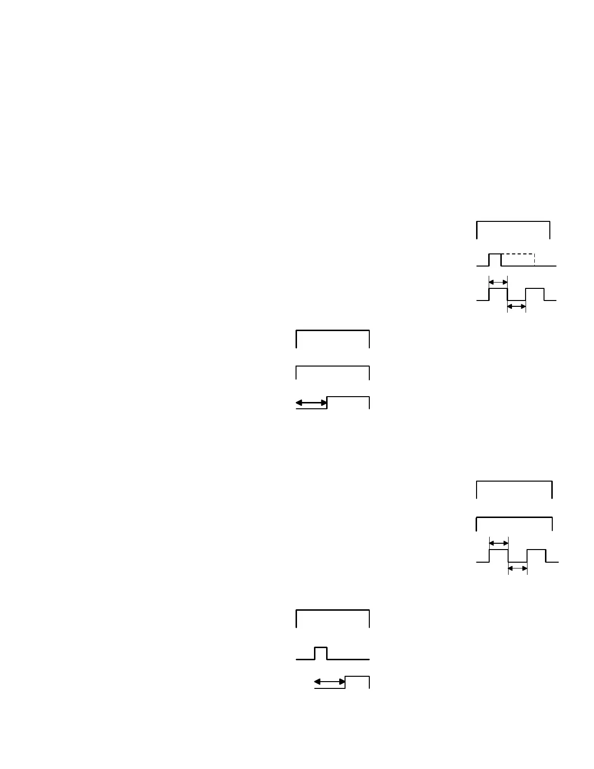
Mode B Repeat Cycle - Signal
Start (50% fixed duty cycle):
Power is continuously applied.
The OFF/ON cycle is initiated at
the leading edge of the start input.
The output relay will be OFF for
the set time and ON for the set
time. The ON and OFF cycle will
continue to alternate until a reset
input is applied or power is
disconnected.
Figure 3
Mode B Repeat Cycle - Power
ON Start/Power-OFF Reset
(50% fixed duty cycle):
Connect
start terminals (3 & 6). Upon
application of power to the timer,
the OFF delay is initated for the
set time and then ON for the set
time. The ON and OFF cycle will
continue to alternate until a reset
input is applied or power is
disconnected.
Figure 4
Mode C
Signal Interval/OFF-delay:
Power is continously applied.
Time delay period begins on both
the leading and trailing edges of
the start input. Output contact
switches during time delay period,
either connecting or disconnecting
load. Once the timer has timed
out from the trailing edge, it resets
and is ready for subsequent start
inputs.
Refer to Figure 5.
Product Operation and Setup Instructions 1A983
Power
2 - 10
ON
OFF
Start 3 - 6
ON
OFF
ON
OFF
Timing
Output
9 - 11
Power
2 -10
ON
OFF
Start 3 -6
ON
OFF
ON
OFF
Timing
Output
9 - 11
Power
2 -10
ON
OFF
ON
OFF
Output
9 - 11
On Time
Off Time
Start 3 - 6
ON
OFF
Power
2 -10
ON
OFF
Start 3 - 6
ON
OFF
ON
OFF
Output
9 - 11
On Time
Off Time
 Loading...


