H3FA
H3FA
142
Installation
Connection
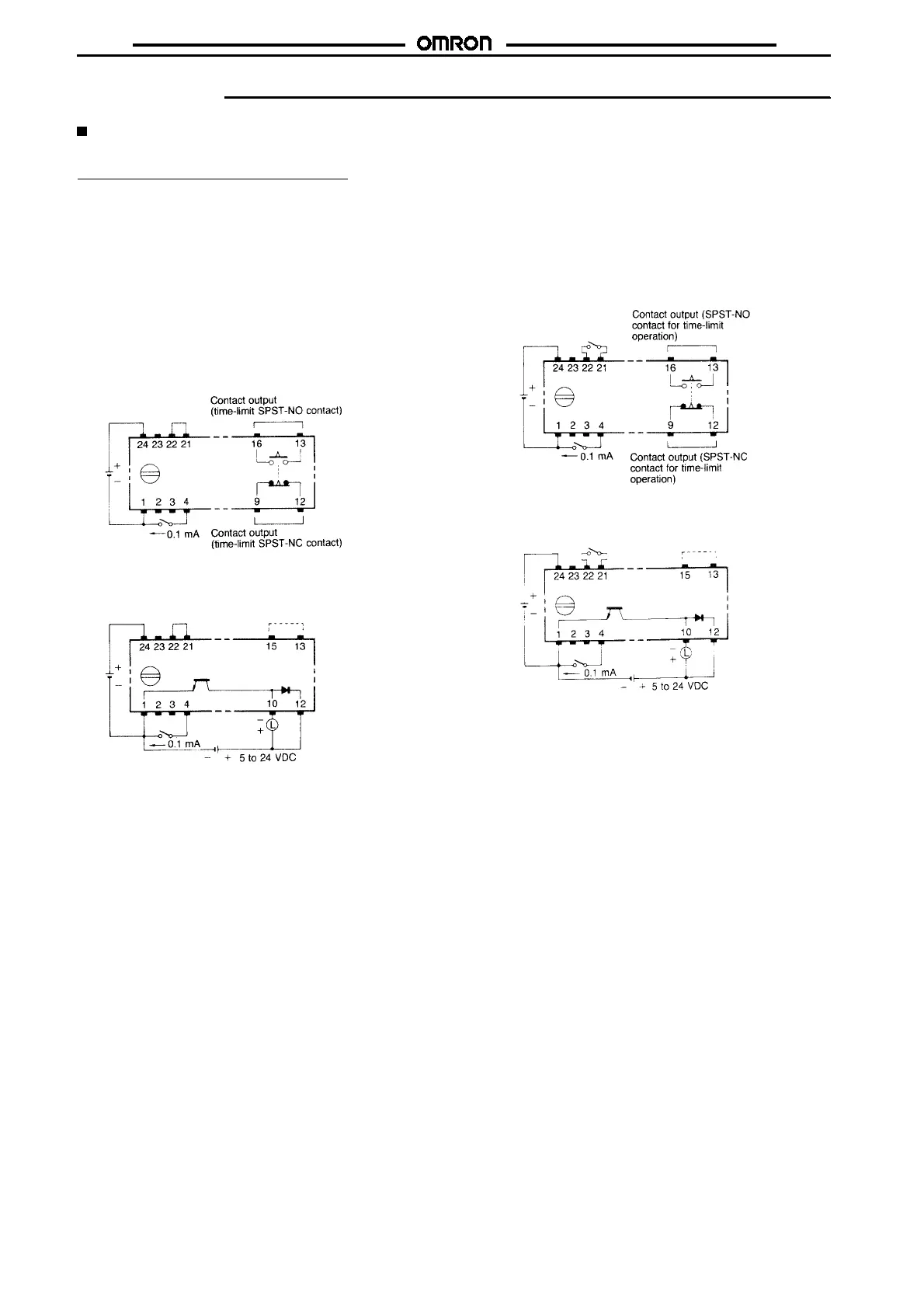
Note: Do not apply voltage to any terminal other than the power supply terminals. Otherwise, the internal circuitry may be damaged.
H3FA-A, H3FA-B, H3FA-SA, H3FA-SB
Standard Operation (ON-delay Operation)
Whenthesettimehaselapsed subsequent tothepowerapplication
(connect power to terminals
A
and
X
, and short-circuit terminals
M
and
O
when a 12/24 VDC-operated model is used with a 12 VDC
power supply), output is produced.
When connecting an external resistorto the time unit, connect it be-
tween terminals
U
and
W
, and open terminals
U
and
V
. Refer to
“Ex-
ternal Resistor and Operate Time”
on page 140.
When operating an external reset input contact short-circuit termi-
nals
A
and
D
. In this case, the current that flows from terminal
D
to
terminal
A
isapprox.0.1mA.Therefore,useofahigh-reliabilitycon-
tact is recommended for the reset input.
Contact Output (Top View)
Solid-state Output (Top View)
When using the 12/24 VDC operated timer with a 24 VDC
power supply, open terminals 13 and 15.
Integration Operation
By opening the terminals connected to the internal variable resistor
(
U
and
V
), or external resistor (
U
and
W
), timer operation can be in-
terrupted to permit the time unit to perform time integration opera-
tions. Reconnecting the terminals enables timer operation to be
continued.
Contact Output (Top View)
Solid-state Output (Top View)
When using the 12/24 VDC operated timer with a 24 VDC
power supply, open terminals 13 and 15.

 Loading...


