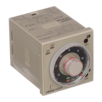
H5AN
H5AN
196
Installation
Terminal Arrangement
Note: Specifications for 12- to 24-VDC, 48-VDC, and 100-VDC
models are listed separately in this datasheet.
Gate input
Reset input
(Internally
connected)
External
power
supply
(0 V)
+12 V
+12 V
Contact output
Unused
Power supply
For DC power
Terminal 1: --
Terminal 2: +
Do not use unused
terminals for relaying.
Leave them open.
Unused
Connections
Power Supply Connection
Connect the required supply voltage to terminals 1 and 2.
AC Power Supply DC Power Supply
Load Connection
Terminals 4, 5, and 6 are for contact output while terminals 12 and
13areforsolid-stateoutput.(Terminal 14isconnectedtoabsorbthe
surge if an inductive load is connected.)
The control outputs of both contact type and solid-state type are si-
multaneously available.
Load Operation
When a Load Operates with Contact Output
When a Load Operates with Solid-state Output
Load 1
Load 2
Load 3

 Loading...