EasyManuals Logo

Omron H3CR-A User Manual

Omron H3CR-A
326 pages
To Next Page IconTo Next Page
To Previous Page IconTo Previous Page
Page #88 background imageLoading...
Page #88 background image
H3DR-A/P/M
H3DR-A/P/M
88
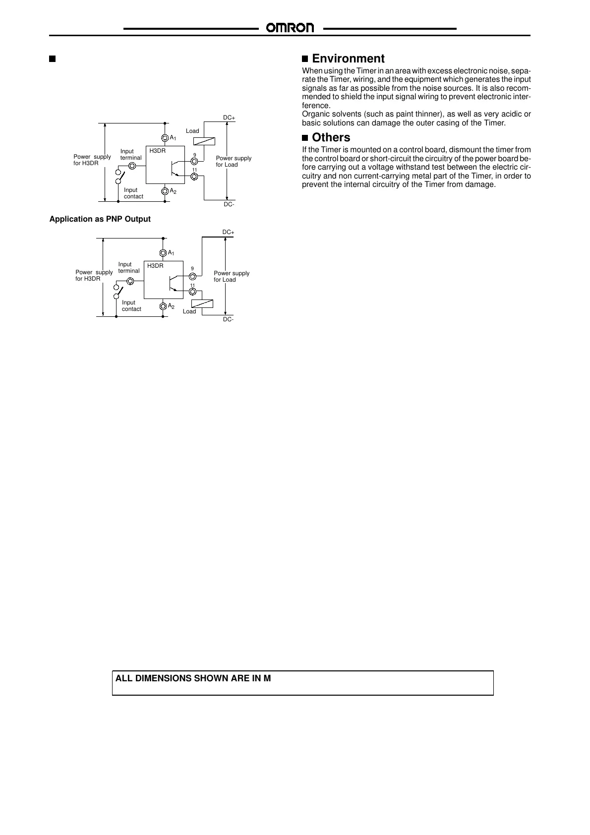
Output Connection of H3DR-AS with
Transistor Output
TheH3DR-AS transistoroutput is insulated fromthe internalcircuit-
ry by a photocoupler, so either NPN or PNP output is possible.
Application as NPN Output

































































Input
terminal
Load
Power supply
for Load
DC+
A
1
A
2
11
Input
contact
9
DC-
Power supply
for H3DR
H3DR
Application as PNP Output
Power supply
for H3DR
11
9
Load
Input
terminal
Input
contact
































































Power supply
for Load
DC+
DC-
H3DR
A
1
A
2
Environment
WhenusingtheTimerinanarea withexcess electronic noise,sepa-
rate the Timer, wiring, and the equipment which generates the input
signals as far as possible from the noise sources. It is also recom-
mended to shield the input signal wiring to prevent electronic inter-
ference.
Organic solvents (such as paint thinner), as well as very acidic or
basic solutions can damage the outer casing of the Timer.
Others
If the Timer is mounted on a control board, dismount the timer from
the control board orshort-circuit the circuitry of the power board be-
fore carrying out a voltage withstand test between the electric cir-
cuitry and non current-carrying metal part of the Timer, in order to
prevent the internal circuitry of the Timer from damage.
ALL DIMENSIONS SHOWN ARE IN MILLIMETERS.
To convert millimeters into inches, multiply by 0.03937. To convert grams into ounces, multiply by 0.03527.
Cat. No. L83-E1-3

Other manuals for Omron H3CR-A

Questions and Answers:

Question and Answer IconNeed help?

Do you have a question about the Omron H3CR-A and is the answer not in the manual?

Omron H3CR-A Specifications

General IconGeneral
Time Range0.05 seconds to 300 hours
Output TypeRelay
Mounting TypeDIN Rail
Operating Temperature-10°C to 55°C
Contact FormSPDT
Number of Pins8
Contact Rating5A at 250VAC
Storage Temperature-25°C to 65°C
TypeSolid State Timer
Dimensions48 mm x 48 mm
Operating ModeON-delay, OFF-delay, Interval, One-shot
Operating Voltage24V DC, 100-240V AC

Related product manuals