H3CR
H3CR
52
Precautions (H3CR-A)
Note: The
undermentioned is common for all H3CR-A models.
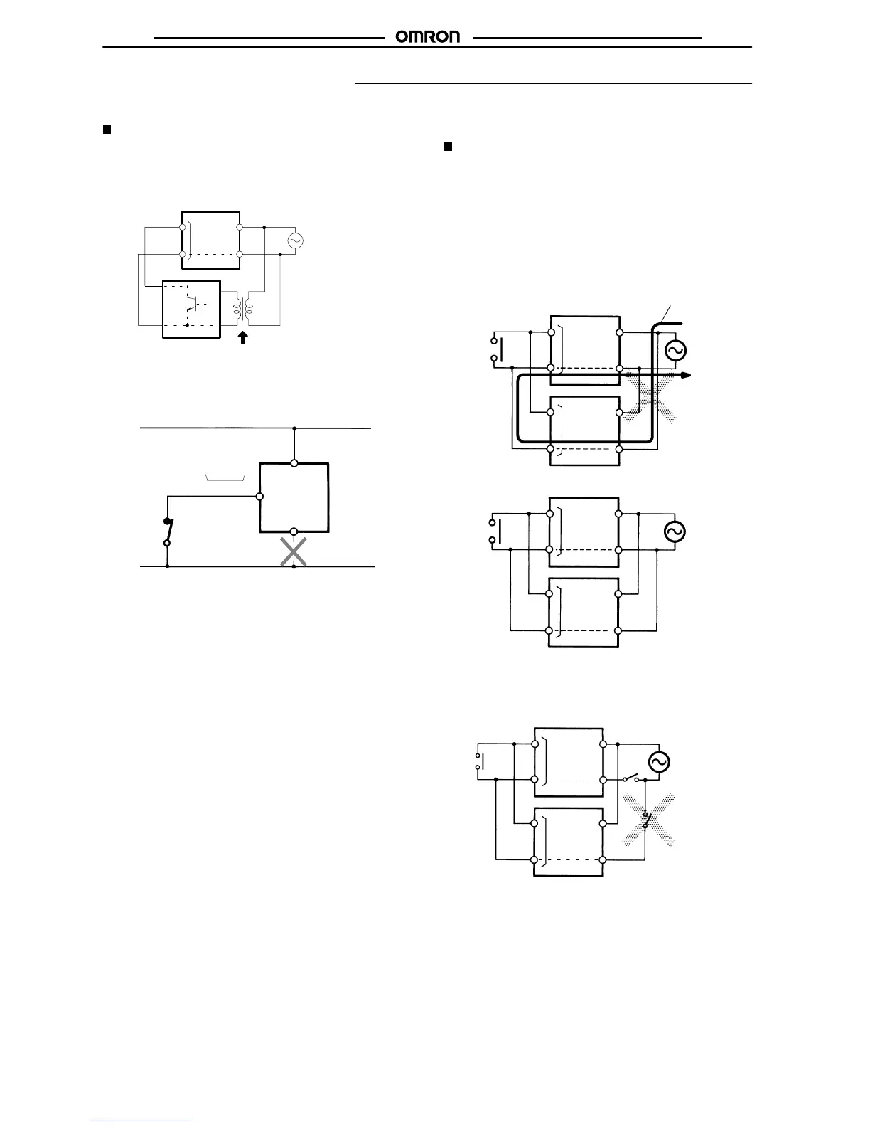
Power Supplies
For
the power supply of an input device of the H3CR-A
j/-AjS/-AP,
use
an isolating transformer with the primary and secondary wind
-
ings
mutually isolated and the secondary winding not grounded.
Example: H3CR-A
H3CR-A
Input
terminal
Power supply
Isolation transformer is required.
Input device
S,G, R
5, 6, 7
2
10
2
The H3CR-Aj/-AjS/AP’s power supply terminal 2 is a common
terminal
for input
signals to the T
imer
. Do not disconnect the wires
on terminal 2, otherwise the internal circuitry of the Timer will be
damaged.
H3CR-A
Input terminal
5, 6, 7
G, S, R
10
2
Make sure that the voltage is applied within the specified range,
otherwise
the internal elements of the T
imer may be damaged.
Input/Output
Relationship between Input and Power Supply
Circuits (except for H3CR-A8E)
The H3CR-A (except for H3CR-A8E) uses transformerless power
supply.
When connecting a relay or transistor as an external signal
input
device, pay attention to the following points to prevent short-
circuiting
due to a sneak current to the transformerless power
sup
-
ply. If a relay or transistor is connected to two or more T
imers, the
input
terminals of those T
imers must be wired properly so that
they
will
not dif
fer in phase, otherwise the terminals will be short-circuited
to
one another
.
Input
terminal
Power supply
H3CR-A
Input
terminal
Contact or transistor for
external input signal
Input
terminal
Power supply
Input
terminal
Incorrect
Correct
Short-circuit current
It is impossible to provide two independent power switches as
shown
below regardless of whether or not
the T
imers are dif
ferent in
phase.
Input
terminal
Power supply
Input
terminal
 Loading...


