H3CR
H3CR
54
Precautions (H3CR-H)
Note: The undermentioned is common for all H3CR-H models.
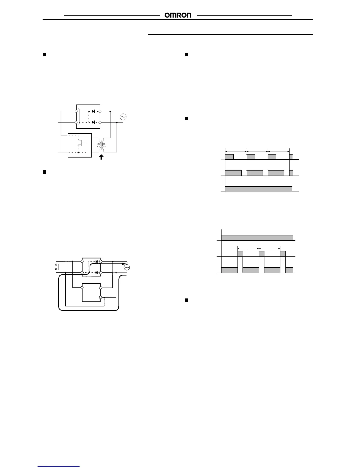
Power Supplies
The H3CR-H has a large inrush current; provide sufficient power
supply
capacity
. If the power
supply capacity is too small, there may
be
delays in turning ON the output.
With
the H3CR-H
j
RL, for the power supply of an input device, use
an
isolating transformer
, of which
the primary and secondary wind
-
ings are mutually isolated and the secondary winding is not
grounded.
Input terminal
H3CR-HjRL
Power supply
Isolation transformer is required.
Input device
10
2
4* 7
1* 5
7*
2*
*
:H3CR-H8RL
Input/Output (H3CR-HjRL)
An
appropriate input is applied to the input signal terminal of the T
im-
er
when the input terminal for the
input signal is short-circuited. Do
not
attempt to connect any
input terminal to any terminal other than
the
input terminal or to apply voltage across other than the specified
input
terminals or the internal
circuits of the T
imer may be damaged.
The H3CR-Hj
RL uses transformerless power
supply
. When con
-
necting
a relay or transistor as an external signal input device, pay
attention
to
the following points to prevent short-circuiting due to a
sneak
current to the transformerless power supply
.
If
input is made simultaneously from one input contact or a transistor
to the H3CR-H and a Timer whose common input terminals are
used
as power terminals, such as the H3CR-A, a short-circuit cur
-
rent
will
be generated. Either input through isolated contacts, or iso
-
late
the power supply for one of the T
imers.
H3CR-HjRL
Short-circuit current
*: H3CR-H8RL
H3CR-A
10 7*
22*
10
2
R.S.
7
6
G.
5
4*
51*
7
Wiring
The
H3CR-H has a high impedance circuit. Therefore, the H3CR-H
may
not be reset if the H3CR-H is influenced by inductive voltage. In
order
to eliminate any influence of inductive voltage, the wires
con
-
nected to the H3CR-H must be as short as possible and should not
be
installed alongside power
lines. If the H3CR-H is influenced by
inductive
voltage that is 30% or more of the rated voltage, connect
a
CR filter with a capacitance of approximately 0.1 µF and a resis-
tance of approximately 120 Ω or a bleeder resistor between the
power
supply terminals. If there is any residual voltage due to cur
-
rent
leakage, connect a bleeder resistor between
the power supply
terminals.
Operation
An
interval of
3 s minimum is required to turn on the H3CR-H after
the
H3CR-H is turned of
f. If the H3CR-H is turned on
and of
f repeat
-
edly with an interval of shorter than 3 s, the internal parts of the
H3CR-H
may deteriorate or the H3CR-H may malfunction.
Power
Output
state
1
3 s min.
Output
state 2
After
the forced reset function of the H3CR-H is activated, an inter
-
val
of 3 s
minimum is required to activate the forced reset function
again.
If the forced reset function is activated repeatedly with an in
-
terval
of shorter than 3 s, the internal parts of the H3CR-H may dete
-
riorate
and the H3CR-H may malfunction.
Power
Reset
input
3 s min.
Output
3 s min.
If
it is required that the output be turned
on repeatedly with an inter
-
val
of shorter than 3 s, consider use of the H3CR-A in mode D (sig
-
nal OFF-delay).
Others
If
the H3CR-H is dropped or experiences some other kind of shock,
because a latching relay is used for output, contacts may be
reversed
or go into a neutral state. If
the H3CR-H is dropped, recon
-
firm
correct operation.
 Loading...


