Solid-state Multi-functional Timer H3DE-M/-S B-57
Timers
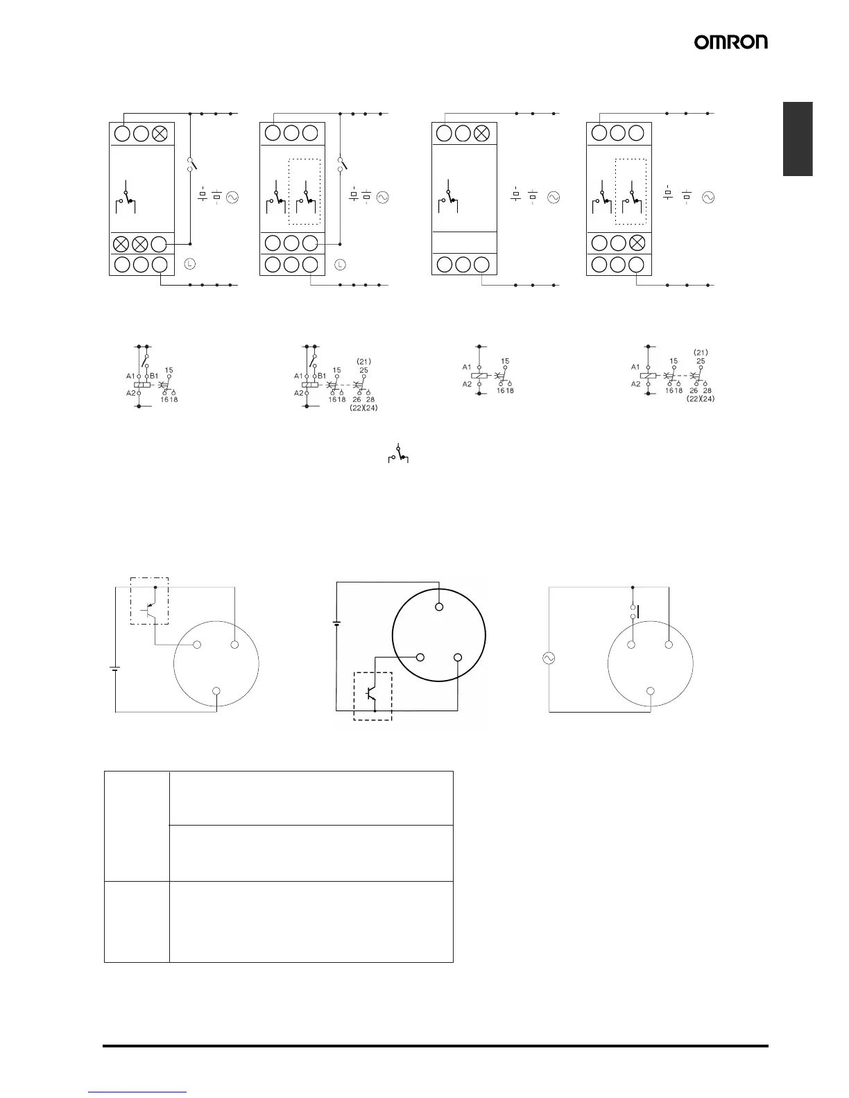
■ Terminal Arrangement
Note: 1. The relay R2 can be set to either instantaneous or time-limit contact using the switch located on the bottom of the Timer.
2. DC supply voltage does not require the designation of polarity.
3. The contact symbol for the H3DE is indicated with because it offers multiple operating modes and is different from the delayed
contact for conventional timers.
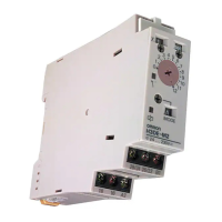
■ Input Connections
The inputs of the H3DE-M1/-M2 are voltage (voltage imposition or open) inputs.
25/2115
R1 R2
18 16
18 16 A2
A1 15
25/2115
R1 R2
18 16
18 16 A2
B1
A1 15
15
R1
18 16
18 16 A2
B1
A1 15
15
R1
18 16
18 16 A2
A1 15
-------------------------------------------------
-------------------------------------------------
-------------------------------------------------
------------
-------------------------------------------------
-------------------------------------------------
-------------------------------------------------
------------
-------------------------------------------------
-------------------------------------------------
-------------------------------------------------
-------------------------------------------------
-------------------------------------------------
-------------------------------------------------
25
/21
28
/24
26
/22
28
/24
26
/22
25
/21
28
/24
26
/22
28
/24
26
/22
(see note 1)(see note 1)
H3DE-M1 H3DE-S1H3DE-M2 H3DE-S2
(see note 2) (see note 2) (see note 2) (see note 2)
(DIN notation) (DIN notation) (DIN notation) (DIN notation)
A1
B1
A2
24 VDC
A1
B1
A2
(+)
(−)
A
1
B1
A
2
24 VDC
(+)
(−)
No-contact Input
(Connection to PNP output sensor.)
Contact Input
Voltage Input Signal Levels
Sensor
Start Start
Operates with PNP transistor ON Operates with relay ON
TimerTimer
No-contact Input
(Connection to NPN output sensor.)
Sensor
Operates with NPN transistor ON
Timer
No-contact
input
Contact
input
1. Transistor ON
Residual voltage: 1 V max.
(Voltage between terminals B
1 and A2 must be more than
the rated "H-level" voltage (20.4 VDC min.).)
2. Transistor OFF
Leakage current: 0.01 mA max.
(Voltage between terminals B
1 and A2 must be less than
the rated "L-level" voltage (2.4 VDC max.).)
Use contacts that can adequately switch 0.1 mA at each
voltage to be imposed. (When the contacts are ON or
OFF, voltage between terminals B
1 and A2 must be within
the following ranges:
When contacts are ON: 20.4 to 253 VAC/DC
When contacts are OFF: 0 to 2.4 VAC/DC