H5CR H5CR
7
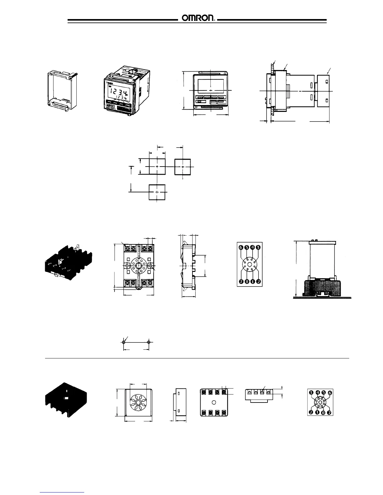
■ PANEL MOUNTING ADAPTER Y92F-30
The diagram below shows the adapter on an H5CR-L timer. The mounting depths for H5CR-B and H5CR-S are the same as shown in
Timer Dimensions
.
6
(0.24)
85.9
(3.38)
Panel
Y92F-30
Panel mounting
adapter
P3G-08
Rear surface
connection socket
58
(2.28)
48
(1.89)
Panel Cutouts
Panel cutouts shown at right
conform to DIN 43700.
60 min.
(2.36)
-0
45
+0.6
-0
45
+0.6
60 min.
(2.36)
Note: 1. The mounting panel thickness
should be 1 to 4 mm (0.04 to 0.16 in).
2. It is possible to mount timers side by
side, but only horizontally.
A = [n x 45 (n -1) x 3.5]
+0.6
-0
■ MOUNTING SOCKETS FOR H5CR-L TIMERS
P2CF-08 Bottom surface or track mounting
Two 4.5 dia.
(0.18)
mounting
holes
7.8
(0.31
50 max.
(1.97)
70 max.
(2.76)
Eight
M3.5 x 7.5
sems
3
(0.12)
4.5
(0.18)
35.4
(1.39)
20 max.
(0.79)
Top view
P2CF-08
92.8
(3.65)
H5CR-L
Two 4.5 dia. (0.18) or two
M4 socket mounting holes
Mounting holes
4
(0.16)
Terminal arrangement
Surface mounting
40 ± 0.2
(1.57)
P3G-08 Back mounting socket
∅27
(1.06)
17.5
(0.69)
45
(1.77)
45
(1.77)
Terminal arrangement
7
(0.28)
8
(0.31)
M3.5
4.5
(0.18)
9
(0.35)

 Loading...


