H5CR H5CR
15
Precautions
■ POWER SUPPLIES
• The input circuit is not isolated from the power supply circuit.
The internal circuit might be damaged by a surrounding AC
circuit, so use an isolated AC power supply with equipment
connected to the input circuit.
• If power is interrupted for less than 10 ms, operation will
continue normally. If power is interrupted for 10 to 500 ms,
operation will be inconsistent, and timing may stop or reset,
depending on the mode.
• Connect the power supply voltage through a relay or switch
in such a way that the voltage reaches a fixed value
immediately.
• Depending on switching frequency, current surges may
degrade relay contacts; relays with a capacity greater than
10 A are recommended.
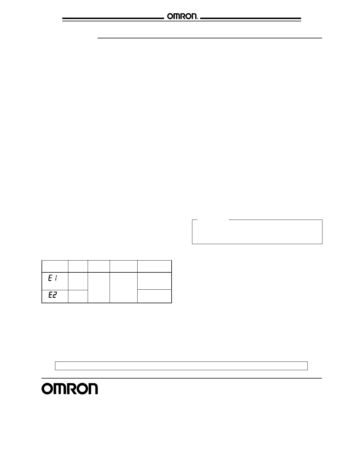
Display Error Output Correction Set
status
CPU OFF Press No
RESET change
key
Memory Set at the
factory
■ CHANGING SET VALUES
• The timer set value can be changed while the timer is
operating, so a high value can be set temporarily to
inactivate the timer, or a low value can be set to activate the
timer more quickly. If the set value is changed accidentally
during operation, the timed output might be activated.
Therefore, turn the key protection input ON unless the set
value is being changed.
• To avoid changing the output when changing the set value, it
is recommended to begin changing the set value by entering
a large number in the higher digit.
• When using the timer in an area with much electrical noise,
separate the timer, wiring, and the equipment which
generates the input signals as far as possible from the noise
sources. It is also recommended to shield the input signal
wiring to prevent electrical interference.
• Organic solvents (such as paint thinner), as well as very
acidic or basic solutions, might damage the outer casing of
the timer.
■ OPERATING ENVIRONMENT
■ MAXIMUM VOLTAGE TEST
• When the timer is installed in a control box and tests are
conducted which may damage the timer's internal circuitry
(for example, a test measuring the maximum voltage
difference between the control circuit and metal
components), remove the timer from the control box or short
circuit the terminals.
CAUTION
■ INPUT AND OUTPUT
• Do not use external sources to increase the voltage of input
signals (control signal, reset, gate, and key protection).
• Be sure that the load of the control output (contact, transistor)
is less than the maximum values indicated in the
specifications. If the output load exceeds the recommended
value, the life span of the contact output type will be
shortened dramatically, and the transistor of the transistor
output type will be damaged.
• The transistor output is opto-isolated from the internal
circuitry, so either NPN or PNP transistors can be used.
This product contains a lithium battery. Lithium batteries
explode if incinerated. Dispose of the digital timer as a
combustible item.
■ SELF-DIAGNOSTIC FUNCTION
• The following displays will appear if an error occurs. The
present value and output enter the same status as after
pressing the RESET key.
OMRON ELECTRONICS LLC OMRON CANADA, INC.
One East Commerce Drive 885 Milner Avenue
Schaumburg, IL 60173 Scarborough, Ontario M1B 5V8
1-800-55-OMRON 416-286-6465
Cat. No. GC TMCN1 3/02 Specifications subject to change without notice. Printed in the U.S.A.
OMRON ON-LINE
Global - http://www.omron.com
USA - http://www.omron.com/oei
Canada - http://www.omron.com/oci
NOTE: DIMENSIONS ARE SHOWN IN MILLIMETERS. To convert millimeters to inches divide by 25.4.

 Loading...


