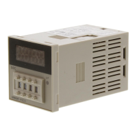
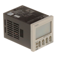
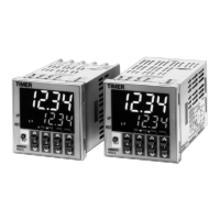
H5CX-B@-N
40
Timing Charts
Note: 1. The forecast value = set value - forecast set value
2. The forecast set value is used to set the deviation for the set value.
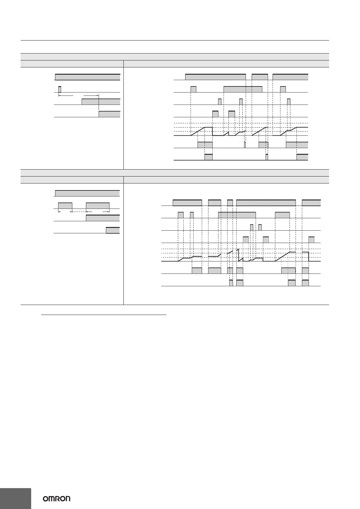
Mode A: Signal ON delay (Timer resets when power comes ON.)
Basic operation Detailed operation
* Start signal input is disabled during timing.
• Timing starts when the start signal goes ON.
• While the start signal is ON, the timer starts when the
power comes ON or when the reset input goes OFF.
• A sustained control output is used.
• Timing stops when the time is up.
Note: Output is instantaneous when the set value is 0.
The names in parentheses are used for the absolute value setting.
Mode F-1: Cumulative (Timer does not reset when power comes ON.)
Basic operation Detailed operation
• Start signal enables timing (timing is stopped when the
start signal is OFF or when the power is OFF).
• A sustained control output is used.
• Timing continues even after the time is up.
Note: Output is instantaneous when the set value is
0.
When the H5CX is used with power start in mode F
mode or F-1 (i.e., cumulative operation with output on
hold), there will be a timer error (approximately 100
ms each time the H5CX is turned ON) due to the
characteristics of the internal circuitry. Use the H5CX
with signal start if timer accuracy is required.
The names in parentheses are used for the absolute value setting.
Power
( ) The names in parentheses are used for the absolute value setting.
*
Start signal input
Timing
Forecast
output
OUT1
(
)
Control
output 1
OUT1
Control
output
OUT2
(
)
Control
output 2
OUT2
Set value (SV 2)
Forecast value
(SV 1)
OUT1
999999
0
OUT2
Power
Start signal
Gate
Reset
Timing diagram
Start signal input
Timing Timing
Sustained
Power
Forecast
output
OUT1
(
)
Control
output 1
OUT1
Control
output
OUT2
(
)
Control
output 2
OUT2
( ) The names in parentheses are used for the absolute value settin
.
0
Set value (SV 2)
Forecast value
(SV 1)
OUT1
999999
OUT2
Power
Start signal
Gate
Reset
Timing diagram


 To Next Page