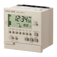
Digital Time Switch H5S 7
Connections
■ Terminal Arrangement
H5S-@A@/-@B@ Flush Mounting Models
(2-circuit models) (4-circuit models)
H5S-@FA@/-@FB@ Surface Mounting Models
(2-circuit models) (4-circuit models)
Note: 1. The Time Switch output uses a no-voltage contact. An external power supply is required for applications in which a load is driven.
2. The output contact ratings are different for 2-circuit and 4-circuit models.
■ Input Connection (2-circuit Models Only)
Use a switch or relay as the input contact.
Use a contact that is capable of operating with 5 V, 0.1 A (with a minimum signal input width of 100 ms).
Note: Input must be selected using the “F2: Input selection” step of initial setting mode. For details, refer to Using Advanced Functions on page 23.
Output 2
Output 1Power
source
Input
+
∼
−
∼
(Rear View)
G
A
H
JI
DCB
Output 2 Output 3
Output 4
Output 1Power
source
+
∼
−
∼
(Rear View)
B
E
D
A
C
F
J
H
G
I
Output 2Input
Output 1
Power
source
−
∼
+
∼
(Front View)
FGH
I
CB
D
E
Output 2Output 3
Output 4
Output 1 Power
source
−
∼
+
∼
(Front View)
B
E
D
A
C
F
J
H
G
I
Flush mounting models
(H5S-@A2@/-@B2@)
Surface mounting models
(H5S-@FA2@/-@FB2@)
G
J
F
I

 Loading...