H8PS
7
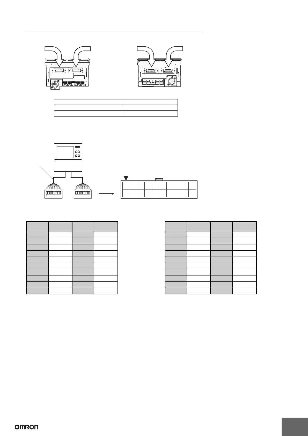
Output Cable Connections (16-/32-output Models Only)
1. E5ZE-CBL200 Connector-type Output Cable (Order Separately) Connections
Output Cable 1 Wiring Table Output Cable 2 Wiring Table
Note: 1.
The COM pins in the output connectors are connected inside the Cam Positioner to the negative terminal of the 24-VDC power supply input.
2.
The Vs pins in the output connectors are connected inside the Cam Positioner to the Vs terminal.
3. The Vs pins in the output connectors are not used on models with NPN outputs.
4.
The COM pins in output connector 1 and output connector 2 are connected to each other inside the Cam Positioner. The Vs pins in output connector 1
and output connector 2 are also connected to each other inside the Cam Positioner.
Output Connector 1 (CN1)
Output Connector 2 (CN2) (See note.)
Output Connector 1 (CN1)
Output Connector 2 (CN2) (See note.)
(Bottom view) (Bottom view)
Note: The 16-output Models do not have CN2 Connectors.
Output Connector Output signals
Output Connector 1 (CN1) Cam 1 to Cam 16, COM, Vs
Output Connector 2 (CN2) (See note.) Cam 17 to Cam 32, COM, Vs
Flush Mounting Models Surface Mounting Models
(CN1)
E5ZE-CBL200
Connector-type
Output Cable
(Order Separately)
H8PS-16@/-32@
(CN2)
XG4M-2030
MIL Connector
(made by OMRON)
1 3 5 7 9 1113151719
2468 10 12 14 16 18 20
Pin Arrangement of XG4M-2030 Connectors
Output
Cable 1
Output
Cable 2
Outputs Connector
pin No.
Outputs Connector
pin No.
Cam 1 20 Cam 9 19
Cam 2 18 Cam 10 17
Cam 3 16 Cam 11 15
Cam 4 14 Cam 12 13
Cam 5 12 Cam 13 11
Cam 6 10 Cam 14 9
Cam 7 8 Cam 15 7
Cam 8 6 Cam 16 5
COM 4 COM 3
Vs 2 Vs 1
Outputs Connector
pin No.
Outputs Connector
pin No.
Cam 17 20 Cam 25 19
Cam 18 18 Cam 26 17
Cam 19 16 Cam 27 15
Cam 20 14 Cam 28 13
Cam 21 12 Cam 29 11
Cam 22 10 Cam 30 9
Cam 23 8 Cam 31 7
Cam 24 6 Cam 32 5
COM 4 COM 3
Vs 2 Vs 1
 Loading...


