http://www.ia.omron.com/
5
(c)Copyright OMRON Corporation 2007 All Rights Reserved.
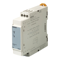
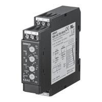
K6EL
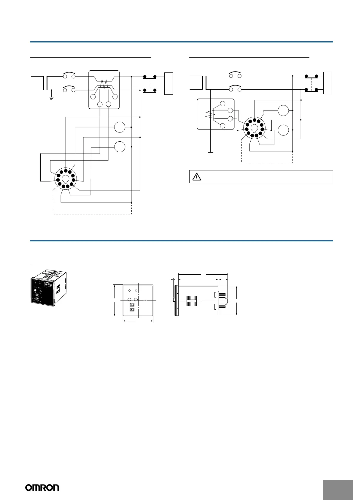
Connection Examples
Installation on the Electrical Path Installation on a Ground Bus Bar
Note: When not using the kt and lt terminals (test terminals), leave
them unconnected. The Relay may not be able to attain its
performance characteristics if used with the kt and lt terminals
connected.
Dimensions
Note: All units are in millimeters unless otherwise indicated.
Ground Fault Relay
Load
Y/b
Auxiliary relay
Alarm buzzer
100/110 VAC
200/220 VAC
Y
BZ
Transformer
Molded case
circuit-breaker
6
5
4
3
2
1
11
10
9
8
7
kt
k
l
lt
OTG ZCT
K6EL
Ground
Fault Relay
ZCT
Do not, under any circumstances, connect the k and l
lines to ground.
100/110 VAC
200/220 VAC
Auxiliary relay
Alarm buzzer
Y
BZ
Load
Y/b
Transformer
Molded case
circuit-breaker
6
5
4
3
2
1
11
10
9
8
7
lt
l
k
kt
OTG ZCT
K6EL Ground
Fault Relay
ZCT
Ground bus bar
48
48
0.7
13.6
44.8 × 44.8
78
63.7
6
1
Applicable Connecting Sockets
P2CF-11 Front Connecting Socket
P3GA-11 Back Connecting Socket
PL11 Back Connecting Socket