2-7
2 System Design
NB-series Programmable Terminals Startup Guide Manual(V109)
2-2 Demonstration System
2
z Addresses allocation table
Memory allocation table
The I/O relays of the PLC are allocated as follows.
Addresses Function Component Name Corresponding Screen
W_bit 0.01 Automatically close
(disabled)
Bit Button Fully Open
W_bit 0.02 Start the maintenance
screen
Bit Button Wait
W_bit 1.00 Open Bit Button/
Bit Lamp
All Screens/Check 2
W_bit 1.01 Stop Bit Button/
Bit Lamp
All Screens/Check 2
W_bit 1.02 Close Bit Button/
Bit Lamp
All Screens/Check 2
LW.B 10.0 Texts on screen flash Bit Lamp Stop
C 0 Counter address Level Meter,
Number Display
Wait, Check 3
T 0 Timer address Number Display Check 3
D 0 Switch Screens PLC Control -
D 11 Output Screen No. PLC Control -
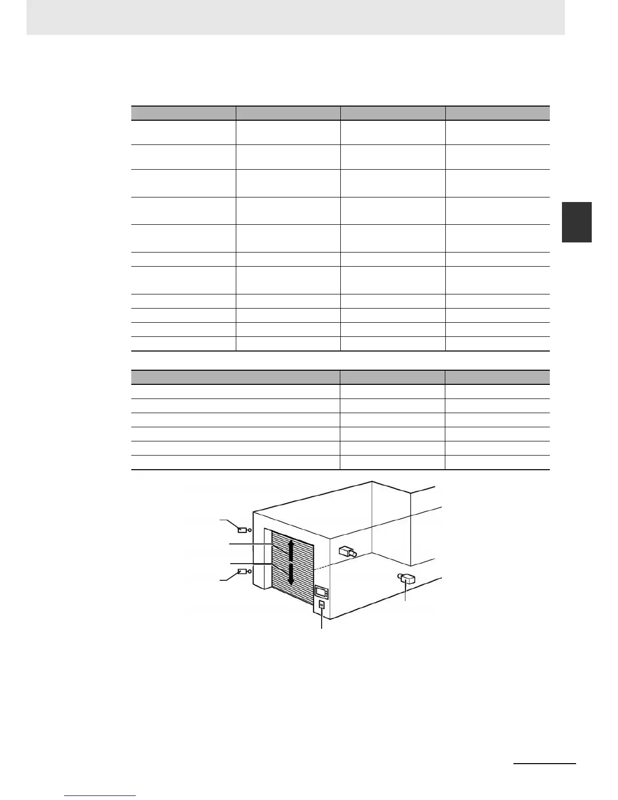
CIO_bit 0.03~0.06 (See the following table) Bit Lamp Check 1
Equipments Contactors Addresses
Vehicle sensor SEN1 0.03
Light sensor SEN2 0.04
Upper limit LS LS1 0.05
Lower limit LS LS2 0.06
Motor for opening control (Rise motor) MO1 100.00
Motor for closing control (Down motor) MO2 100.01
LS1(0.05)
MO1(100.00)
MO2(100.01)
LS2(0.06)
SEN2(0.04)
SEN1(0.03)

 Loading...


