New H7ET
11
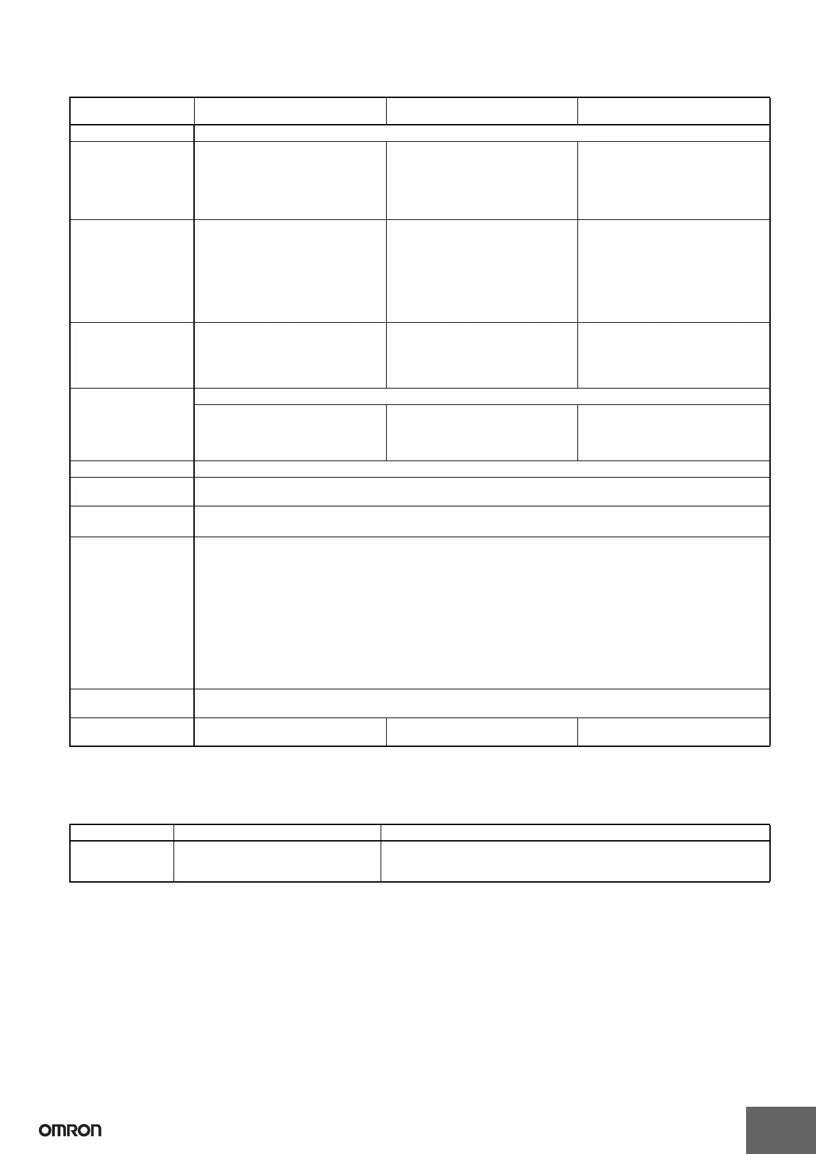
■ Characteristics
Note: 1. Industrial electromagnetic environment (EN/IEC 61326-1 Table 2)
2. Weight includes waterproof packing and flush mounting bracket.
■ Reference Value
Item H7ET-NV@-@
H7ET-NV@-H@
H7ET-NFV@-@ H7ET-N@-@
Time accuracy ±100 ppm (25°C)
Insulation resistance 100 MΩ min. (at 500 VDC) between
current-carrying metal parts and ex-
posed non-current-carrying metal
parts, and between the backlight pow-
er supply and timer input terminals/re-
set terminals for backlight models
100 MΩ min. (at 500 VDC) between
current-carrying metal parts and ex-
posed non-current-carrying metal
parts and between timer input termi-
nals and reset terminals
100 MΩ min. (at 500 VDC) between
current-carrying metal parts and ex-
posed non-current-carrying metal
parts
Dielectric strength 1,000 VAC, 50/60 Hz for 1 min between
current-carrying metal parts and ex-
posed non-current-carrying metal
parts and between the backlight power
supply and timer input terminals/reset
terminals for backlight models
3,700 VAC, 50/60 Hz for 1 min between
timer input terminals and exposed non-
current-carrying metal parts
2,200 VAC, 50/60 Hz for 1 min between
reset terminals and exposed non-cur-
rent-carrying metal parts and between
timer input terminals and reset termi-
nals
1,000 VAC, 50/60 Hz for 1 min between
current-carrying metal parts and ex-
posed non-current-carrying metal
parts
Impulse withstand
voltage
4.5 kV between current-carrying termi-
nal and exposed non-current-carrying
metal parts
4.5 kV between current-carrying termi-
nal and exposed non-current-carrying
metal parts
3 kV between timer input terminals and
reset terminals
4.5 kV between current-carrying termi-
nal and exposed non-current-carrying
metal parts
Noise immunity Square-wave noise generated by noise simulator (pulse width: 100 ns/1 μs, 1-ns rise)
±600 V (Between timer input terminals/
Between reset terminals)
±480 V (Between the backlight power
supply terminals for backlight models)
±1.5 kV (Between timer input termi-
nals)
±500 V (Between reset terminals)
±500 V (Between timer input terminals/
Between reset terminals)
Static immunity ±8 kV (malfunction)
Vibration resistance Malfunction: 0.15-mm single amplitude at 10 to 55 Hz for 10 min each in 3 directions
Destruction: 0.375-mm single amplitude at 10 to 55 Hz for 2 hrs each in 3 directions
Shock resistance
Malfunction: 200 m/s
2
3 times each in 6 directions
Destruction: 300 m/s
2
3 times each in 6 directions
EMC (EMI) EN61326-1 (See note 1.)
Emission Enclosure: EN55011 Group 1 class B
(EMS) EN61326-1 (See note 1.)
Immunity ESD: EN61000-4-2: 4 kV contact discharge (level 2)
8 kV air discharge (level 3)
Immunity RF-interference from AM Radio Waves:
EN61000-4-3: 10 V/m (80 MHz to 1 GHz) (level 3)
Immunity RF-interference from Pulse-modulated Radio Waves:
EN61000-4-3: 10 V/m (900 MHz ± 5 MHz) (level 3)
Immunity Conducted Disturbance: EN61000-4-6: 10 V (0.15 to 80 MHz) (level 3)
Immunity Burst: EN61000-4-4: 2 kV power line (level 3)
2 kV I/O signal line (level 4)
Degree of protection Front panel: IP66, NEMA4 with waterproof packing
Terminal block: IP20
Weight (see note 2.) No-backlight model: Approx. 60 g
Backlight model: Approx. 65 g
Approx. 60 g Approx. 60 g
Item Value Note
Battery life 10 years min. with continuous input at
25°C (lithium battery)
The battery life is calculated according to the conditions in the left column and
therefore is not a guaranteed value. Use these value as reference for mainte-
nance or replacement.

 Loading...


