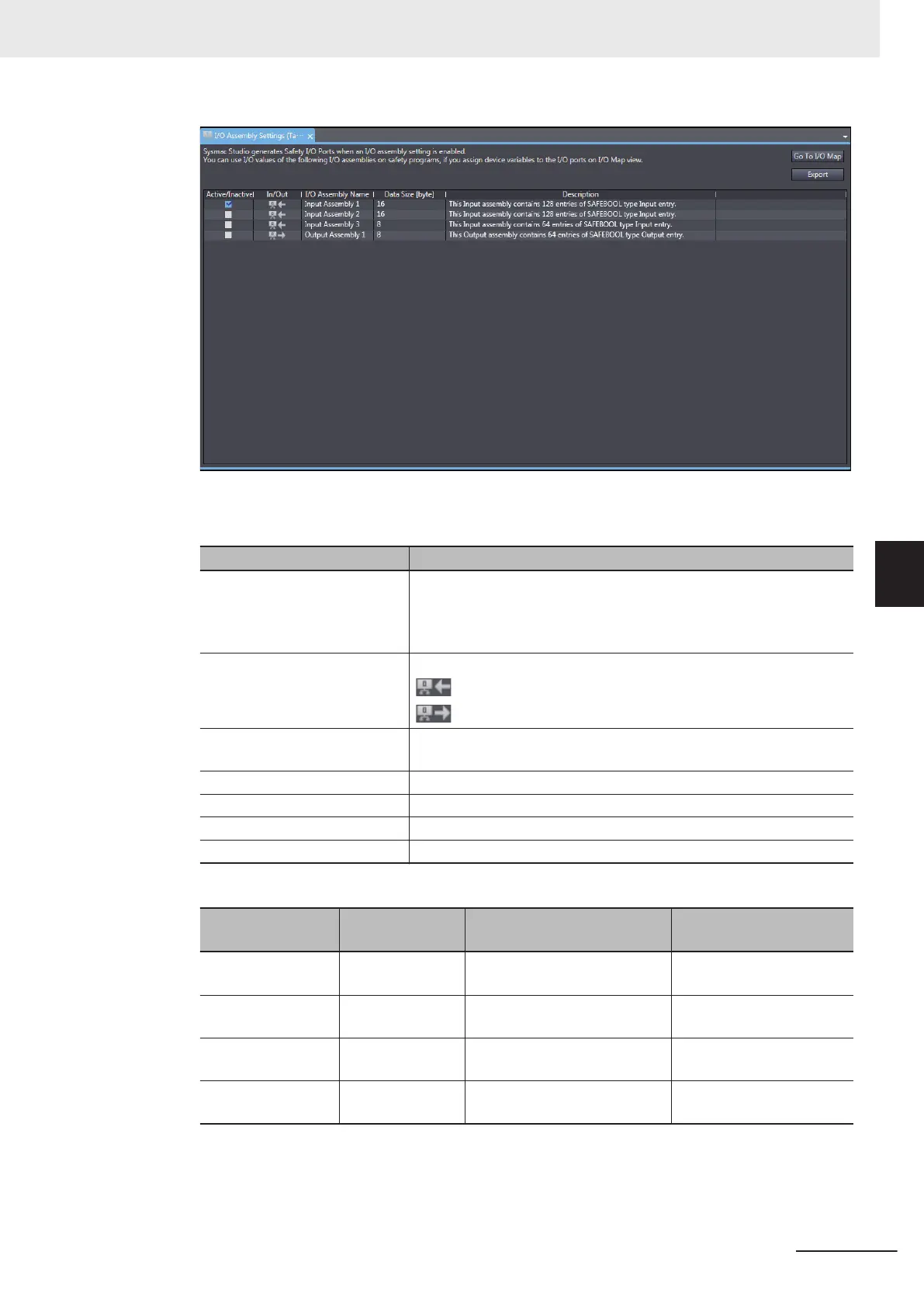
The I/O Assembly Settings (Target) Tab Page consists of the items shown in the following ta-
ble.
Item Description
Active/Inactive Use this box to enable or disable each I/O Assembly. When you ena-
ble the assembly
, a port is added to the I/O Map.
Selected: I/O Assembly is enabled.
Not selected: I/O Assembly is disabled.
In/Out Shows the data direction of each I/O Assembly
.
: In – Data sent to the originator device.
: Out – Data received from the originator device.
I/O Assembly Name The name of each I/O Assembly is displayed. It is same as the port
name displayed on the I/O Map.
Data Size [byte] The byte size of each I/O Assembly is displayed.
Description The description of each I/O Assembly is displayed.
Go To I/O Map Button Click this button to open the I/O Map Tab Page.
Export Button Exports the target device settings as a file (extension .tds).
The following lists the types of selectable I/O Assembly.
Name
Assembly num-
ber
Data direction Size
InputAssembly 1 768(0x300) Input – Data sent to the origi-
nator device
16 bytes (SAFEBOOL ×
128)
InputAssembly 2 769(0x0301) Input – Data sent to the origi-
nator device
16 bytes (SAFEBOOL ×
128)
InputAssembly 3 770(0x0302) Input – Data sent to the origi-
nator device
8 bytes (SAFEBOOL × 64)
OutputAssembly 1 928(0x03A0) Output – Data received from
the originator device
8 bytes (SAFEBOOL × 64)
The activated I/O Assembly is displayed as a port on the I/O map of the originator device to communi-
cate with as shown below. Y
ou can use it on a safety program by assigning a variable to the I/O port.
5 System Configuration and Setup
5 - 19
NX-series Safety Control Unit User's Manual (Z930)
5-4 Setting Up the Safety Process Data Communications
5
5-4-2 Setting Up the CIP Safety Communications