4-3
4-1 Installation Conditions
OMNUC G5-series AC Servomotors and Servo Drives User’s Manual (with Built-in EtherCAT Communications)
4
System Design
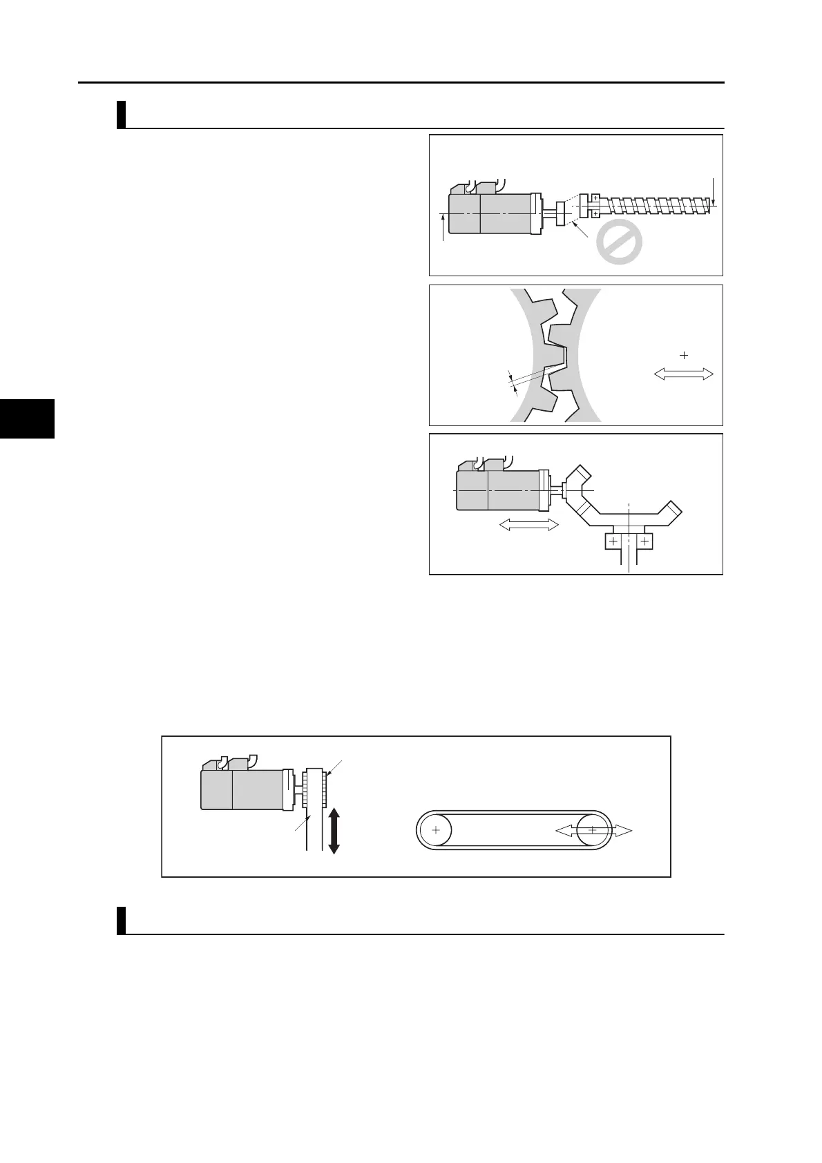
Connecting to Mechanical Systems
For the allowable axial loads for motors,
refer to Characteristics on page 3-2. If an
axial load greater than that specified is
applied to a motor, it may reduce the limit of
the motor bearings and may break the motor
shaft.
When connecting to a load, use couplings
that can sufficiently absorb mechanical
eccentricity and declination.
For spur gears, an extremely large radial
load may be applied depending on the gear
precision. Use spur gears with a high degree
of precision (for example, JIS class 2:
normal line pitch error of 6 µm max. for a
pitch circle diameter of 50 mm).
If the gear precision is not adequate, allow
backlash to ensure that no radial load is
placed on the motor shaft.
When using bevel gears, a load is applied in
the thrust direction depending on the
structural precision, the gear precision, and
temperature changes. Provide appropriate
backlash or take other measures to ensure
that a thrust load larger than the specified
level is not applied.
Do not put rubber packing on the flange
surface. If the flange is mounted with rubber
packing, the motor flange may crack under the tightening force.
When connecting to a V-belt or timing belt, consult the manufacturer for belt selection and tension.
A radial load twice as large as the belt tension will be placed on the motor shaft. Do not allow a
load that exceeds the allowable radial load to be placed on the motor shaft. If an excessive radial
load is applied, the motor shaft and bearings may be damaged.
Set up a movable pulley in the middle of the motor shaft and the load shaft so that the belt tension
can be adjusted.
Water and Drip Resistance
The protective structure for the motors is as follows:
Equivalent to IP67 (except for through-shaft parts)
Set a movable structure.
Bevel gear
Set a structure in which
the distance between
axes can be adjusted.
Backlash
Motor center line
Ball screw center line
Axial offset
Axial offset
Pulley
Belt
Tension
Tension adjustment (Set a movable structure.)
 Loading...
