Power Supply Technical Information 9
Power
supplies
Power Supply Precautions for Correct Use
■Installation
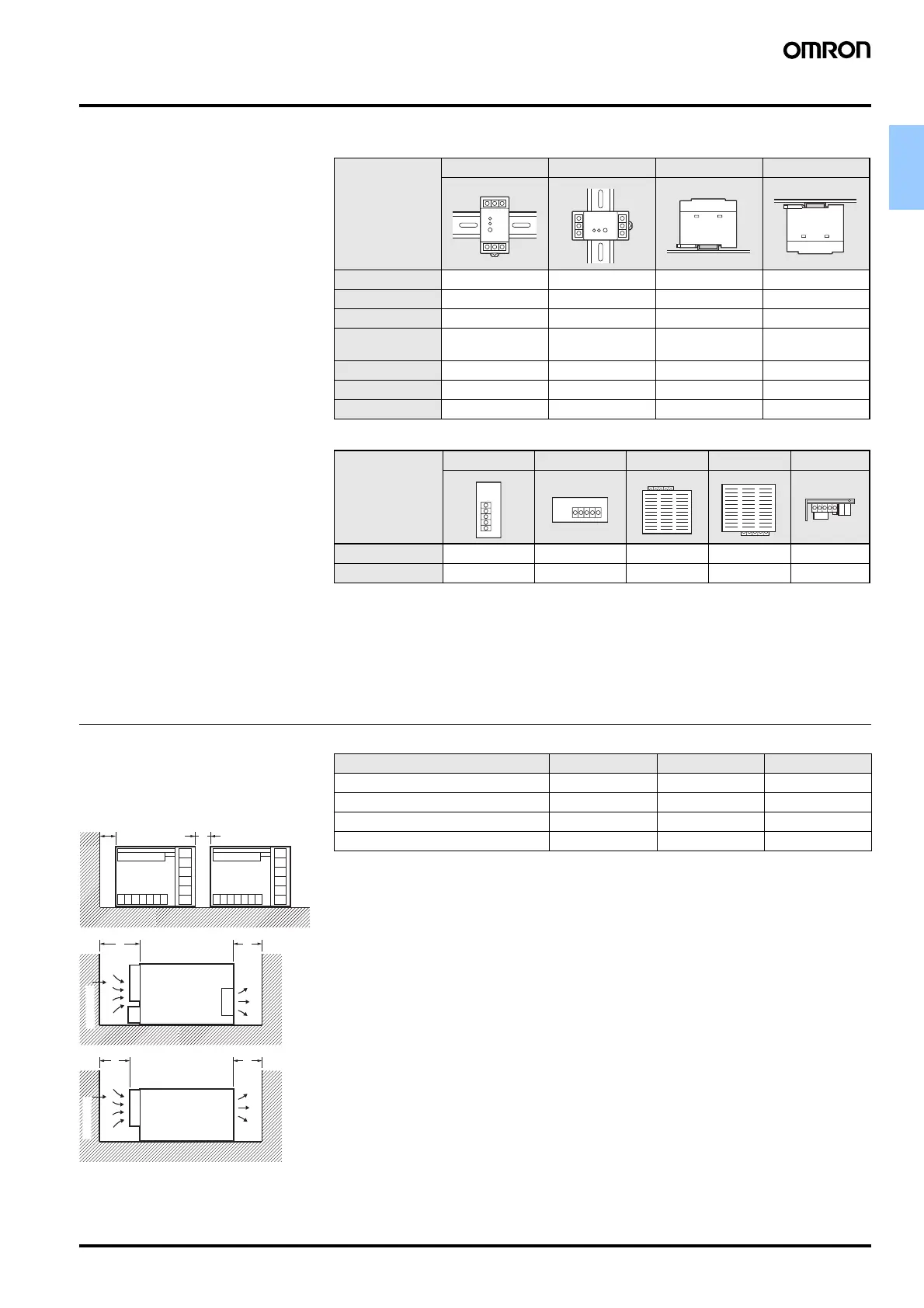
● Mounting Methods
The standard mounting methods should
be used to ensure proper heat
dissipation. If other mounting methods
must be used, the ambient temperature
must be lowered or the load rate must
be reduced to prevent temperature
increase inside the Power Supply
caused by poor heat dissipation.
Refer to the information in the table on
the right.
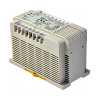
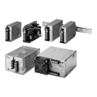
DIN-rail Mounting Models: Main Models
Screw Mounting Models: Main Models
*1. The 300-W model can be used under given
conditions.
*2. The 600-W model can be used.
Yes: Can be used
No: Cannot be used.
Conditional: Can be used at an ambient tempera-
ture of 50° C (up to 50% of load rate).
Mounting direction Standard Horizontal Face-up Face-down
Model
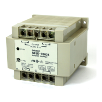
S82K OK No Conditional No
S8TS OK No No No
S8VS(15, 30W) OK No OK No
S8VS (60, 90, 120,
180, 240 W)
OK No No No
S8T-DCBU-01 OK No No No
S8T-DCBU-02 OK No No No
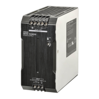
S8VM OK No No No
Mounting direction Standard Horizontal Face-up Face-down Horizontal
Model
S82J Yes Yes *1 Conditional *2 Conditional *2 No
S8VM Yes Yes Yes No No
● Installation Space
When mounting two or more Power
Supplies side by side, be sure to provide
spacing between them as indicated in
the table on the right or greater.
Note. Be sure to provide an installation space that
allows for shielding (including ducts).
A
A
BC
Fan
Fan
S82J
BC
Front panel
Front panel
Spacing Required Between Power Supplies (Unit: mm)
* Ambient temperature of 50° C: 100 mm
Model Dimension A Dimension B Dimension C
S82J 20 20 (300, 600 W) 20 (300, 600 W)
S82K 10 --- ---
S8VS 20 --- ---
S8VM 20 --- ---
 Loading...