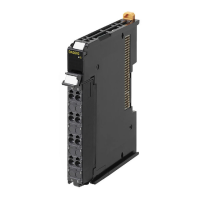
Do you have a question about the Omron SYSMAC C200H-MAD01 and is the answer not in the manual?
Outlines general rules for product operation and usage in specific applications.
Details warnings about handling units while power is supplied and potential electric shock.
Lists places where the control system should not be operated due to environmental factors.
Provides crucial precautions for applying and using the PC and its units safely and correctly.
Lists the general and performance specifications for the C200H-AD003 Analog Input Unit.
States that general specifications conform to other series models.
Details performance specifications like input/output ranges, resolution, accuracy, and power.
Shows input specifications with conversion value graphs for different signal ranges.
Provides information on terminal arrangements, internal circuitry, and wiring examples.
Provides a wiring example for connecting input devices to the C200H-AD003 unit.
Details how to use various functions like setting inputs, reading values, and processing data.
Explains how to specify analog inputs to be used and their signal ranges via DM bits.
Describes how to read analog input conversion values stored in IR words using the user program.
Explains how to compute the mean value of analog input conversion values using history buffers.
Describes the function to hold the maximum digital conversion value for each input.
Explains how to detect input circuit disconnections for specific signal ranges.
Explains the procedure for adjusting offset and gain for accurate input calibration.
Provides a flow diagram for adjusting offset and gain using the adjustment mode.
Details the procedures for specifying input numbers and adjusting offset and gain.
Covers troubleshooting procedures, error detection, and handling for the unit.
Provides a step-by-step procedure for troubleshooting Analog Input Unit errors.
Lists errors detected by the Analog Input Unit and their corresponding error codes and countermeasures.
Explains errors detected by the CPU Unit related to Special I/O Units, including error flags.
Explains how output setting errors are stored and used as execution conditions.
Explains the procedure for adjusting offset and gain for accurate output calibration.
Details the procedures for specifying output numbers and adjusting offset and gain.
Covers troubleshooting procedures, error detection, and handling for the output units.
Provides a step-by-step procedure for troubleshooting Analog Output Unit errors.
Lists errors detected by the Analog Output Unit and their corresponding error codes and countermeasures.
Explains errors detected by the CPU Unit related to Special I/O Units, including error flags.
Explains how to detect input circuit disconnections for specific signal ranges.
Explains how output setting errors are stored and used as execution conditions.
Explains the unit's ratio conversion function for analog-to-analog conversions.
Explains the procedure for adjusting offset and gain for accurate I/O calibration.
Details the procedures for specifying input numbers and adjusting offset and gain.
Details the procedures for specifying output numbers and adjusting offset and gain.
Explains how to adjust the analog output offset to reach a standard value.
Explains how to adjust the analog output gain to maximize the output value.
Covers troubleshooting procedures, error detection, and handling for the Analog I/O Unit.
Provides a step-by-step procedure for troubleshooting Analog Input Unit errors.
Lists errors detected by the Analog I/O Unit and their corresponding error codes and countermeasures.
Explains errors detected by the CPU Unit related to Special I/O Units, including error flags.
| Type | Analog I/O Module |
|---|---|
| Operating Temperature | 0 to 55°C |
| Storage Temperature | -20 to 75°C |
| Input Voltage Range | 0-10V |
| Output Voltage Range | 0-10V |
| Input Signal Range | 4-20 mA |
| Isolation | Photocoupler |
| Power Supply | 5 VDC |
| Weight | 200 g |
| Conversion Time | 10ms per channel max |


