Appendix BChanges From Earlier Models
112
Error Codes
Error codes have been provided for the C200H-AD003. DM area setting errors and errors during operation are
stored in the IR area when the ERR indicator lights. (Refer to 2-7-2 Errors Detected by Analog Input Unit.)
BROKEN WIRE Indicator
The C200H-AD003 does not have a BROKEN WIRE indicator. It uses the ERR indicator, error code, and Discon-
nection Detection Flag to indicate a disconnection in the input wiring. Notification of disconnections can only be
used with an input range of 1 to 5 V or 4 to 20 mA.
Differences Between C200H-DA003/004 and C200H-DA001/002
Functions
Conversion Permission Setting
With the C200H-DA003/004, in contrast to the C200H-DA001/002, use designation outputs must be set in
advance to “1: Use.”
Output Hold Function
This function has been provided for the C200H-DA003/004. (Refer to 3-5-2 Output Hold Function.)
Offset and Gain Adjustment Functions
These functions have been provided for the C200H-DA003/004. (Refer to 3-6 Offset and Gain Adjustment.)
Output Range
The voltage and current can be converted for up to ±5% of the full output range.
Analog Output Values
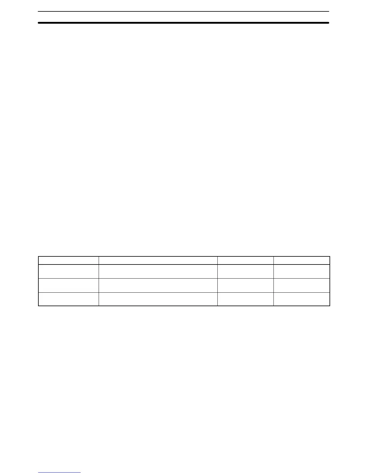
The following table shows the analog output values. Digital set values are shown as 16-bit binary data.
Input signal range DA003 DA002 DA001
–10.0 to 10.0 V F830 to 07D0
(–11.0 to 11.0 V: F768 to 0898)
8FFF to 0FFF ---
0 to 10 V 0000 to 0FA0
(–0.5 to 10.5 V: FF38 to 1068)
0000 to 0FFF 0000 to 0FFF
1 to 5 V / 4 to 20 mA 0000 to 0FA0
(0.8 to 5.2 V / 3.2 to 20.8 mA: FF38 to 1068)
0000 to 0FFF 0000 to 0FFF
Note The figures shown in parentheses are full-scale ±5%.
Error Codes
Error codes have been provided for the C200H-DA003/004. DM area setting errors and errors during operation
are stored in the IR area when the ERR indicator lights. (Refer to 3-7-2 Errors Detected by Analog Output Unit.)