Appendix CSample Programs
118
• DM Area Setting
DM0000: 00C8
DM0001: (Used for calculation)
DM0002: 0100
DM0003: 0000
DM0004: 0500
DM0005: 1130
Digital value for –5%
Conversion value +C8 (-5% portion)
Lower limit: BCD
Lower limit +C8 (-5% portion): BIN
Upper limit: BCD
Upper limit +C8 (-5% portion): BIN
Used with SCL instruction
Sample Program 6: Binary-to-BCD Conversion
A/D conversion values (16-bit binary data) are converted into signed BCD data. The “signed BCD” data refers to
BCD data that is indicated by 7-digit data and 1-digit sign (0: +; F: –).
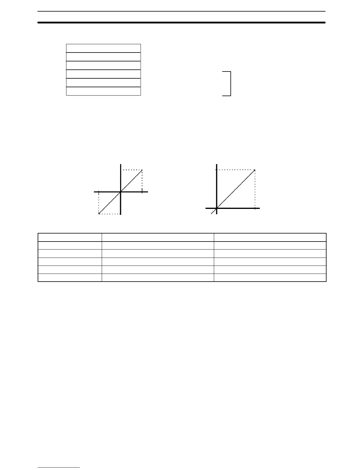
• Conversion Graph (Horizontal Axis: Input Voltage, Vertical Axis: BCD Data)
00002000
F0002000
10 V (07D0)
–10 V (F830)
00004200
F0002000
–0.5 V (FF38)
10.5 V (1068)
Input signal range: –10 to 10 V Input signal range: 0 to 10 V
Unit Settings
Item Setting contents Actual settings
Unit C200H-AD003 ---
Unit number #0 Unit number switch: 0
Operation mode Normal mode Back-panel DIP switch: All OFF
Input 1 used --- DM 1000 = 0001
Input signal range Input number 1, 0 to 10 V DM 1001 = 0001