F-168 General-purpose Basic Switch Z
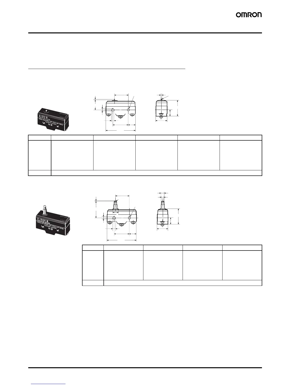
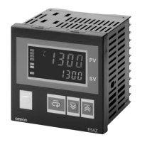
Dimensions
Note: 1. Unless otherwise indicated, all units are in millimeters.
2. Unless otherwise specified, a tolerance of ±0.4 mm applies to all dimensions.
■ Dimensions and Operating Characteristics
Basic Models (General-purpose) & Split-contact Models
The models, illustrations, and graphics are for screw-terminal models (-B). The “-A” at the end of the model number for solder terminal models has
been omitted. For details of the terminals, refer to Terminals above.
Z-15G-B Z-15H-B Z-15E-B Z-01H-B Z-10FY-B
OF
RF min.
PT max.
OT min.
MD max.
2.45 to 3.43 N
{250 to 350 gf}
1.12 N {114 gf}
0.4 mm
0.13 mm
0.05 mm
1.96 to 2.75 N
{200 to 280 gf}
1.12 N {114 gf}
0.3 mm
0.13 mm
0.025 mm
6.12 to 7.85 N
{625 to 800 gf}
1.12 N {114 gf}
0.8 mm
0.13 mm
0.13 mm
2.45 N {250 gf} max.
0.78 N {80 gf}
0.5 mm
0.13 mm
0.04 mm
4.46 to 7.26 N
{455 to 740 gf}
1.12 N {114 gf}
0.8 mm
0.13 mm
0.1 mm
OP 15.9±0.4 mm
4.2
+0.075
−0.025
PT
OP
25.4±0.1 11.9
49.2
23.3±0.25
9.2
24.2
17.45±0.2
Pin Plunger
4.2
+0.075
dia. hole
−0.025
2.3 dia.
2.3SR (see note)
4.36
+0.1
dia.
−0.05
Note: Stainless-steel plunge